EMERSON I&M Sheet Series 158 v9948 ASCO
Summary
Essential manual for professional installation and maintenance of Pipe Thread Adapters designed for _158A Combustion Valve Trains in fuel gas service. This comprehensive guide details assembly, connecting adapters to piping of various sizes (3/4”–3”), proper torque specifications, leak testing, and O-ring replacement procedures. It ensures that technicians can safely and correctly manage the connection of valves and actuators, minimizing service interruption while guaranteeing reliable performance within your combustion system.
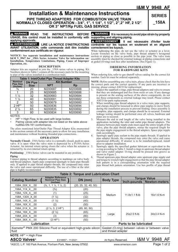
Page 1 Text Content
I&M V_9948_AF
Installation & Maintenance Instructions
SERIES
PIPE THREAD ADAPTERS FOR COMBUSTION VALVE TRAIN
NORMALLY CLOSED OPERATION - 3/4”, 1”, 1 1/4”, 1 1/2”, 2”,2” HF, 2 1/2” _158A
OR 3” NPT/Rp FUEL GAS SERVICE
WARNING WARNING
READ THE INSTRUCTIONS BEFORE It is necessary to avoid pipe strain by properly
USAGE, this control must be installed in conformity with supporting and aligning piping. applying approvals.
AVERTISSEMENT Il est nécessaire d'éviter toute
AVERTISSEMENT LIRE LA NOTICE D’INSTRUCTIONS contrainte sur les tuyaux en soutenant et en alignant AVANT UTILISATION, cette commande doit être installée correctement les tuyaux. conformément aux certificats en vigueur. When tightening the pipe, do not use the valve or actuator as a lever.
Locate wrenches on the valve body, pipe thread adapter’s hexagonal
NOTICE: See separate installation and maintenance instructions
section or piping as close as possible to the pipe joint. The valve train
I&M V_9947 for _158A Series Actuator Valve for information on:
assembly must be checked for external leakage at piping connections and
Installation, Temperature Limitations, Piping, Cause of Improper
at gasket (O-ring) seal face after installation. (See Figure 1).
Operation, etc.
DESCRIPTION ORDERING INFORMATION
Adapter kits are required to join the _158A series valves to piping. Kit
FOR HARDWARE KITS
Numbers shown in Table 1 contain all the necessary parts for the mounting
to pipe of the valves installed in a combustion train. When ordering kits, refer to gas shutoff valves catalog for the correct kit number. Each kit must be ordered separately.
Table 1: Inlet/Outlet Pipe Thread Adapter Kits Nominal Kit Number NOTE: Before assembling any valve train, please check that the kits have DN Pipe Pipe Size the correct parts and the correct quantity. If any parts are incorrect or
Size NPT Rp
(inches)
missing, please contact ASCO for replacement.
3/4 M200687 M200688 1. Inspect the supplied o-rings, pipe thread adapters and valve to ensure
M200685 M200686 that they are undamaged and free from nicks or cuts. If any damage 1 1/4 M200683 M200684 is present on the sealing surfaces of the above components, do not use these components as external leakage may result. Please contact
ASCO for parts replacement.
2. When installing pipe thread adapters in a valve train, pipe supports,
2 HF* M200836 M200694 and clamps should be loosened to allow pipe nipples to move freely
2 1/2 M200835 M200692 during the installation process to prevent binding. Once assembly is complete, pipe supports, and clamps should be re-secured. External
leakage testing should be performed once all valves, hardware and
NOTES:
pipes are re-secured.
• HF* = High Flow, to be used with large bodies 3. Measure the end to end length of the valve being installed in the • Pairing valves with adaptor kits not listed on the table above application including the inlet and outlet pipe thread adapters. The
nullifies EN-161 conformance. distance between pipe nipple ends must equal the entire length of the valve, plus the pipe thread adapters, minus the required length for
The afore mentioned Inlet/Outlet Pipe Thread Adapter Kits enumerated
the pipe nipple engagement in the thread adapters. Space pipe nipple
in this section contain all the necessary parts to allow for easy installation
ends accordingly.
and maintenance without breaking threaded pipe connections.
4. Sparingly apply pipe sealant to the pipe nipple threads. If applied to
OPERATION pipe adapter threads, the compound may enter the valve and cause
Normally Closed:_158A Series valve is a normally closed, push-to-open operational difficulty. If strainer is to be installed/replaced, install valve. It is open when the valve stem is depressed by a P159A Series prior to adaptor installation. Actuator. An internal return spring closes the valve when the actuator is 5. Sparingly apply the specified gasket lubricant or equivalent to the retracted by its own internal return spring. o-ring according to Table 2. Install o-rings in upstream thread adapter
and valve outlet adapter. O-ring should be pressed into groove as
Positioning: _158A Series valves can be mounted in any position.
shown in Figure 2.
Piping
6. Thread upstream pipe thread adapter onto upstream pipe nipple end
Connect piping to thread adapters according to markings on valve body
and torque to wrench tight engagement so that the pipe thread adapter
and thread adapters. Apply pipe compound sparingly to male pipe threads
bolt pattern is in a corresponding orientation with the required
only. If applied to pipe thread adapter threads, the compound may enter
pipe thread bolt pattern orientation. Use hex profile of pipe thread
the valve and cause operational difficulty. The use of a filter at the inlet pipe is highly recommended.
Table 2: Torque and Lubrication Chart
Adapter Reference
Torque Value
Catalog Number ( ) Nominal Pipe Size DN (mm) Body Type
(inches) Inch-pounds Newton-meters
Medium 11.8±1.1 ft-lb 16±1.6 N-m
_158A_130X_X_00 (1 1/4) (32) _158A_14X_X__00 (1 1/2) (40) _158A_16X_X__00 (2) (50) _158A_01X_X__00 (2 1/2, 3, 2 HF*) (65, 80, 50) _158A_18X_X__00 (2 1/2) (65)
Large 25±2.5 ft-lb 34±3.4 N-m
_158A_20X_X__00 (3) (80) _158A_36X_X__00 (2 HF*) (50)
Lubrication Parts to be lubricated
Xiameter® PMX 200 Silicone Fluid or equivalent high-grade silicon Gasket (O-ring) between valves or between valve fluid and thread adapter
NOTE: HF* = High Flow ASCO Valves® E318857 - 11/2021 All Rights Reserved. I&M V_9948_AF ©ASCO, L.P. 160 Park Avenue, Florham Park, New Jersey 07932 www.emerson.com Page 1 of 2
Page Summary Contents For EMERSON I&M Sheet Series 158 v9948 ASCO
Manual Details
| Brand | Emerson |
|---|---|
| Pages | 2 |
| File Size | 673.93 KB |
| Published | June 03, 2026 |
Enter the captcha to get the download link:

Frequently Asked Questions
What safety warning applies when tightening pipe connections?
Do not use the valve or actuator as a lever; locate wrenches on the hexagonal section of the adapter or piping instead.
How do I ensure I have the correct parts when starting the installation?
You must order specific Inlet/Outlet Pipe Thread Adapter Kits listed in Table 1. Always check that all supplied parts match the required kit number.
What should I inspect before using o-rings or thread adapters?
Inspect components for damage; if any nicks, cuts, or signs of damage are found on the sealing surfaces, contact ASCO for replacement parts.
How do I verify that the installed valve system has no leaks?
External leakage testing must be performed once all valves and hardware are installed using a seam test or specialized leak detection equipment.