Delta TAP-CP01 DeviceNet Power Tap Box Installation Manual
Summary
The TAP-CP01 is a specialized DeviceNet Power Distribution Box designed to ensure reliable networking by integrating two 7.5A fuses, robust power input, and an adjustable 121 Ohm termination resistor switch. This manual serves as a comprehensive guide detailing the unit's electrical specifications, operational functions, secure installation on DIN rails, proper wiring techniques (including grounding procedures), and essential safety precautions. It is specifically intended for qualified professional personnel—such as industrial electricians or technicians—who are responsible for installing, maintaining, expanding, or troubleshooting critical DeviceNet automation networks.
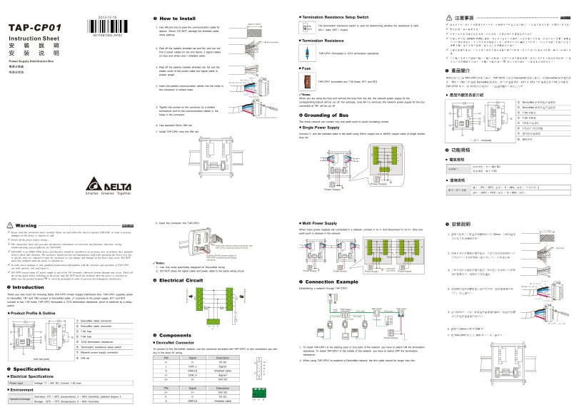
Page 1 Text Content
Termination Resistance Setup Switch 繁體中文
How to Install 注意事項
Approx. 30mm 請在使用前,務必仔細閱讀本使用手冊,並按照本手冊指示進行操作,以免造成產品受損,或導致人員受傷。
ON The termination resistance switch is used for determining whether the resistance is valid.
① Use efficient tool to peel the communication cable for
OFF ON = Valid; OFF = Invalid 實施配線,務必關閉電源。
approx. 30mm. DO NOT damage the shielded cable
while peeling. 本使用說明書僅提供電氣規格、功能規格、安裝配線及周邊裝置部分說明。
本機為開放型 (OPEN TYPE) 機殼,因此使用者使用本機時,必須安裝於具防塵、防潮及免於電擊∕衝擊意
Shielded cable Termination Resistance 外的外殼配線箱內。另必須具備保護措施(如:特殊的工具或鑰匙才可打開),防止非維護人員操作或意外
② Peel off the metallic shielded net and foil, and you will
find 2 power cables (in red and black), 2 signal cables TAP-CP01 formulates a 121Ω termination resistance. 護。 (in blue and white) and 1 shielded cable.
③ Peel off the exterior metallic shielded net, foil and the
plastic cover of the power cable and signal cable in 產品簡介 proper length.
Black (V-) 謝謝您使用台達 TAP-CP01 電源分接盒。TAP-CP01 定義為 Device Net 電源分接 盒,為 Device Net 提供網路電
Blue (CAN_L)
Shielded cab le (CAN_SHLD) TAP-CP01 formulates two 7.5A fuses, EF1 and EF2. 源。TB1 TB2 用於連接 Device Net 匯流排,J1 用於連接 電源,EF1 EF2 用於連接兩個 7.5A 的熔斷器。
④ Insert the peeled communication cables into the holes in TAP-CP01 集成一個 121Ω 的終端電阻,並通過開關來切換是否有效。 the connector in correct order.
Red (V+) Notes:
White (CAN_H) 產品外觀及各部介紹
When you are using the fuse and remove the fuse from the slot, the network power supply for the
corresponding branch will be cut off. For example, once EF1 is removed, the network power supply for the bus 71.2 53.9 1 Device Net 匯流排通訊連接器 [2.80] [2.12]
connected at TB1 will be cut off.
⑤ Tighten the screws on the connector by a slotted 2 Device Net 匯流排通訊連接器 screwdriver and fix the communication cables in the
holes in the connector. Grounding of Bus
Screw by a slotted screwdriver. 4 7.5A 熔斷器
The entire network can contain only one earth point to avoid circulating current. 終端電阻
⑥ Use standard 35mm DIN rail.
Single Power Supply 6 終端電阻設置開關
⑦ Install TAP-CP01 onto the DIN rail.
Connect V- and the shielded cable to the earth using 25mm copper net or 8AWG copper cable of length shorter 7 網路電源連接器
than 3m.
尺寸單位:mm [inch] 8 DIN 軌槽
EF2 EF1
電壓規格:11 ~ 25V DC
V+ SV-
V+ V- 環境規格 Power Supply V+
ic k/ ti bl V-
Power Supply 操作∕儲存環境
⑧ Insert the connector into TAP-CP01. Multi Power Supply
ENGLISH 安裝說明
Warning
When many power supplies are connected in a network, connect V- to V- and disconnect V+ to V+. Only one 大約 30mm
Please read this instruction sheet carefully before use and follow the sheet to operate TAP-CP01 in order to prevent earth point is allowed in the network.
damages on the device or injuries to staff. ① 請使用專業工具將通訊電纜剝開大約 30mm,在剝線過程
Switch off the power before wiring. V- V- V- V-
This instruction sheet only provides introductory information on electrical specifications, functions, wiring, ic k/ in ab le
Insert the communicat ion connector into
trouble-shooting and peripherals for TAP-CP01. TAP-CP01 communication terminal. 遮蔽線
TAP-CP01 is an OPEN-TYPE device and therefore should be installed in an enclosure free of airborne dust, humidity, V+ V+ V+ V+
EF2 EF EF2 EF1 ② 剝開外層的金屬遮罩網和鋁箔,你會看到 根電源線(紅
electric shock and vibration. The enclosure should prevent non-maintenance staff from operating the device (e.g. key Connect 24VDC power supply to
or specific tools are required to open the enclosure) in case danger and damage on the device may occur. DO NOT TAP-CP01 network power supply Disconnect V+ 色和黑色)、2 根訊號線(藍色和白色)、1 根遮罩線。 connector. J1 J1
touch any terminal when the power is switched on.
Notes: V+ SV- V+ SV-
In order not to damage it, only qualified professional staff familiar with the structure and operation of TAP-CP01 V+ V+ V+ V+
can stall, operate, wire and repair it. 1. Use only wires specifically designed for Device Net wiring. V- V- V- One earth V-
2. DO NOT place the signal cable and power cable in the same wiring circuit. Power Supply Power Supply Power Supply point only. Power Supply ③ 去除外層的金屬遮罩網和鋁箔,然後剝去電源線以及訊號
DO NOT connect input AC power supply to any of the I/O terminals; otherwise serious damage may occur. Check all
the wiring again before switching on the power and DO NOT touch any terminal when the power is switched on. Make sure the ground terminal is correctly grounded in order to prevent electromagnetic interference.
Electrical Circuit 黑色(V-)
Connection Example 藍色(CAN_L)
遮蔽線(CAN_SHLD)
Introduction V- V- Establishing a network through TAP-CP01: ④ 將剝開的通訊電纜按照正確的順序嵌入通訊連接器的線
Thank you very much for choosing Delta TAP-CP01 Power Supply Distribution Box. TAP-CP01 supplies power 孔內,如右圖所示。
to Device Net. TB1 and TB2 connect to Device Net cable. J1 connects to the power supply. EF1 and EF2 紅色(V+)
白色(CAN_H)
connect to two 7.5A fuses. TAP-CP01 formulates a 121Ω termination resistance, which is switched by a setup switch. V+ V+
EF2 EF1
Product Profile & Outline
71.2 53.9 1 Device Net cable connector [2.80] [2.12]
2 Device Net cable connector V+ SV- J1 ⑥ 請使用 35mm 的標準 DIN 軌。
3 7.5A fuse
Components ⑦ 將 TAP-CP01 固定在 DIN 軌上,如下圖所示:
4 7.5A fuse 5 121Ω termination resistance Device Net Connector 6 Termination resistance setup switch ① To install TAP-CP01 at the starting point or end point of the network, you have to switch ON the termination
To connect to the Device Net network, use the connector enclosed with TAP-CP01 or any connectors you can
resistance. To install TAP-CP01 in the middle of the network, you have to switch OFF the termination
7 Network power supply connector buy in the store for wiring.
resistance.
Unit: mm [inch] 8 DIN rail PIN Signal Description
② When using TAP-CP01 to establish a Device Net network, the thin cable cannot be longer than 6m.
V- V- 0V DC V+
TB L CAN_L Signal-
Specifications S SHIELD Shielded cable
H CAN_H Signal+ V-
Electrical Specifications
V+ V+ 24V DC
Power Input Voltage: 11 ~ 25V DC; Current: 7.5A max
PIN Signal Description
Environment
V+ V+ 24V DC
Operation: 0o C ~ 55o C (temperature), 5 ~ 95% (humidity), pollution degree 2 V- V- 0V DC
Operation/storage V- SV+
Storage: -25o C ~ 70o C (temperature), 5 ~ 95% (humidity) S SHIELD Shielded cable
Page Summary Contents For Delta TAP-CP01 DeviceNet Power Tap Box Installation Manual
Manual Details
| Brand | Delta |
|---|---|
| Pages | 2 |
| File Size | 761.75 KB |
| Published | June 05, 2026 |
Enter the captcha to get the download link:
