Dell Inspiron BTS721L1 User Guide Manual
Summary
Infineon BTS721L1 PROFET Smart Four-Channel Highside Power Switch datasheet featuring N-channel vertical power FETs with charge pump and diagnostic feedback in Smart SIPMOS technology. Specifications include 43V overvoltage protection, 5.0-34V operating range, 100/50/25m-ohm RDS(on) for one/two/four channels, 8A current limitation, and P-DSO-20 package for automotive and industrial load switching.
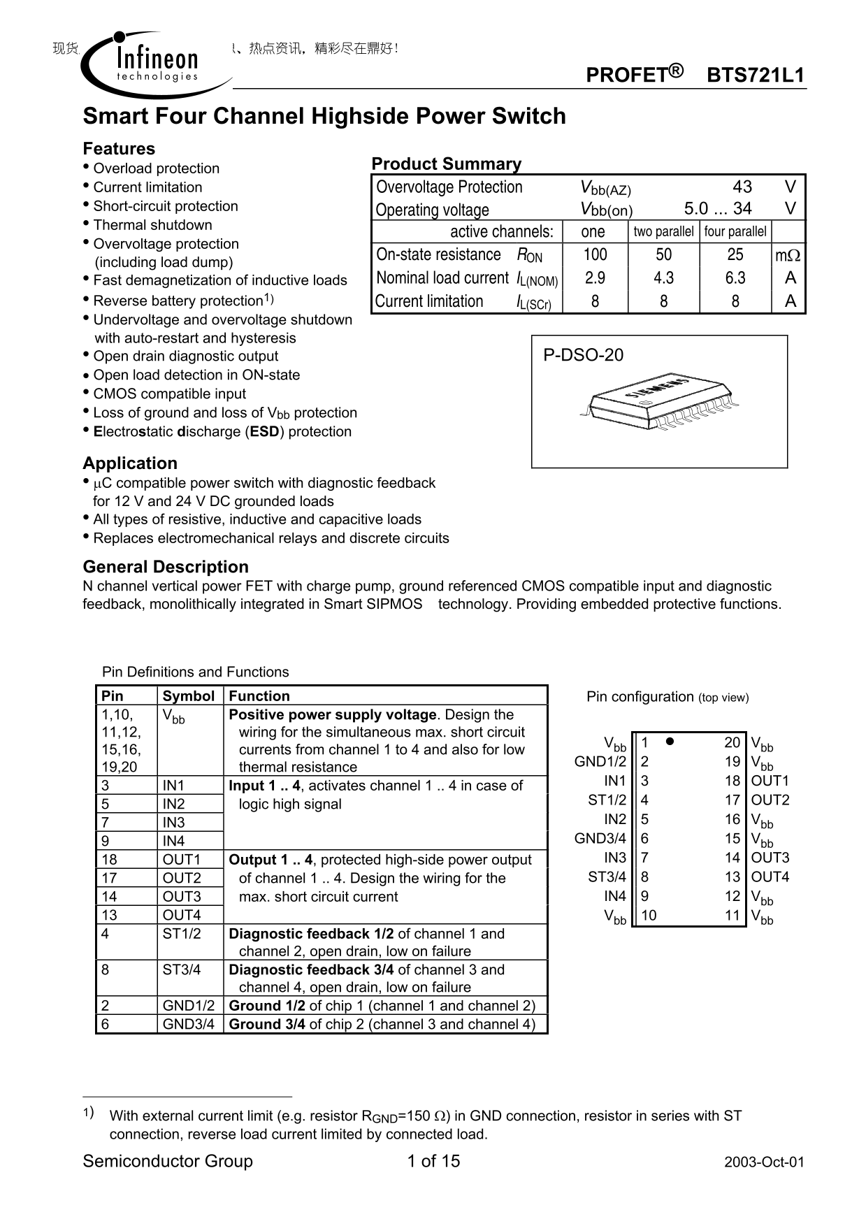
Page 1 Text Content
PROFET® BTS721L1
Smart Four Channel Highside Power Switch Features
• Overload protection Product Summary
• Current limitation Overvoltage Protection Vbb(AZ) 43 • Short-circuit protection
Operating voltage Vbb(on) 5.0 ... 34
• Thermal shutdown
active channels: one two parallel four parallel
• Overvoltage protection
On-state resistance RON 100 50 25 mΩ
(including load dump) • Fast demagnetization of inductive loads Nominal load current IL(NOM) 2.9 4.3 6.3 A • Reverse battery protection1)
Current limitation IL(SCr) 8 8 8 A
• Undervoltage and overvoltage shutdown with auto-restart and hysteresis • Open drain diagnostic output P-DSO-20 • Open load detection in ON-state • CMOS compatible input • Loss of ground and loss of Vbb protection • Electrostatic discharge (ESD) protection
Application • µC compatible power switch with diagnostic feedback for 12 V and 24 V DC grounded loads • All types of resistive, inductive and capacitive loads • Replaces electromechanical relays and discrete circuits
General Description N channel vertical power FET with charge pump, ground referenced CMOS compatible input and diagnostic feedback, monolithically integrated in Smart SIPMOS technology. Providing embedded protective functions.
Pin Definitions and Functions Pin Symbol Function Pin configuration (top view)
1,10, Vbb Positive power supply voltage. Design the
11,12, wiring for the simultaneous max. short circuit
Vbb 1 • 20 Vbb
15,16, currents from channel 1 to 4 and also for low
GND1/2 2 19 Vbb
19,20 thermal resistance
IN1 3 18 OUT1
3 IN1 Input 1 .. 4, activates channel 1 .. 4 in case of
ST1/2 4 17 OUT2
5 IN2 logic high signal
IN2 5 16 Vbb
7 IN3
9 IN4 GND3/4 6 15 Vbb 18 OUT1 Output 1 .. 4, protected high-side power output IN3 7 14 OUT3 17 OUT2 of channel 1 .. 4. Design the wiring for the ST3/4 8 13 OUT4 14 OUT3 max. short circuit current IN4 9 12 Vbb
13 OUT4 Vbb 10 11 Vbb 4 ST1/2 Diagnostic feedback 1/2 of channel 1 and
channel 2, open drain, low on failure
8 ST3/4 Diagnostic feedback 3/4 of channel 3 and
channel 4, open drain, low on failure
2 GND1/2 Ground 1/2 of chip 1 (channel 1 and channel 2) 6 GND3/4 Ground 3/4 of chip 2 (channel 3 and channel 4)
1) With external current limit (e.g. resistor RGND=150 Ω) in GND connection, resistor in series with ST connection, reverse load current limited by connected load.
Semiconductor Group 1 of 15 2003-Oct-01
Page Summary Contents For Dell Inspiron BTS721L1 User Guide Manual
Manual Details
| Brand | Dell |
|---|---|
| Pages | 15 |
| File Size | 357.73 KB |
| Published | July 03, 2026 |
Enter the captcha to get the download link:

Frequently Asked Questions
What types of loads can this power switch handle?
It is compatible with all types of resistive, inductive, and capacitive loads for both 12V and 24V DC grounded applications.
How does the module signal an electrical failure?
A diagnostic feedback output (ST) uses open drain technology and signals 'low' when a fault occurs within its respective channels.
What is the maximum total nominal load current for four active channels?
When all four channels are operating in parallel, the supported nominal load current capacity is 6.3 A.