ABB Procontrol P14 89MS04 R1100 Protection Cabinet for 2 Stations, Remote Bus (EMC-Version) Manual
Summary
This EMC-proven protection cabinet provides a secure, modular enclosure for industrial automation control systems, housing three stations each supporting up to 50 I/O modules. Designed with natural cooling and redundant power capability via an RS485 remote bus, it ensures reliable operation in demanding environments. This manual offers comprehensive guidance on mechanical installation, electrical design, ventilation requirements, and necessary accessories, making it essential for automation engineers and system integrators building robust machine control solutions.
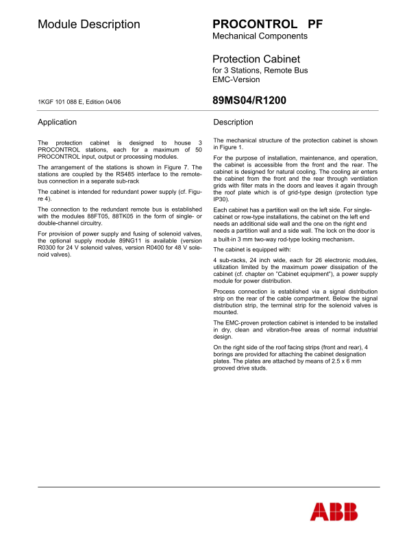
Page 1 Text Content
Module Description PROCONTROL PF
Mechanical Components
Protection Cabinet for 3 Stations, Remote Bus
EMC-Version
1KGF 101 088 E, Edition 04/06 89MS04/R1200
Application Description
The mechanical structure of the protection cabinet is shown
The protection cabinet is designed to house 3
in Figure 1.
PROCONTROL stations, each for a maximum of 50 PROCONTROL input, output or processing modules. For the purpose of installation, maintenance, and operation,
the cabinet is accessible from the front and the rear. The
The arrangement of the stations is shown in Figure 7. The
cabinet is designed for natural cooling. The cooling air enters
stations are coupled by the RS485 interface to the remote-
the cabinet from the front and the rear through ventilation
bus connection in a separate sub-rack
grids with filter mats in the doors and leaves it again through
The cabinet is intended for redundant power supply (cf. Figu- the roof plate which is of grid-type design (protection type re 4). IP30). The connection to the redundant remote bus is established Each cabinet has a partition wall on the left side. For single- with the modules 88FT05, 88TK05 in the form of single- or cabinet or row-type installations, the cabinet on the left end double-channel circuitry. needs an additional side wall and the one on the right end
needs a partition wall and a side wall. The lock on the door is
For provision of power supply and fusing of solenoid valves,
the optional supply module 89NG11 is available (version a built-in 3 mm two-way rod-type locking mechanism.
R0300 for 24 V solenoid valves, version R0400 for 48 V sole-
The cabinet is equipped with:
noid valves).
4 sub-racks, 24 inch wide, each for 26 electronic modules, utilization limited by the maximum power dissipation of the cabinet (cf. chapter on ”Cabinet equipment”), a power supply module for power distribution. Process connection is established via a signal distribution strip on the rear of the cable compartment. Below the signal distribution strip, the terminal strip for the solenoid valves is mounted. The EMC-proven protection cabinet is intended to be installed in dry, clean and vibration-free areas of normal industrial design. On the right side of the roof facing strips (front and rear), 4 borings are provided for attaching the cabinet designation plates. The plates are attached by means of 2.5 x 6 mm grooved drive studs.
Page Summary Contents For ABB Procontrol P14 89MS04 R1100 Protection Cabinet for 2 Stations, Remote Bus (EMC-Version) Manual
Manual Details
| Brand | EMC |
|---|---|
| Pages | 16 |
| File Size | 552.22 KB |
| Published | June 03, 2026 |
Enter the captcha to get the download link:

Frequently Asked Questions
What environment is best for installing this protection cabinet?
It must be installed in a dry, clean, and vibration-free area of normal industrial design.
How much clearance is necessary for proper ventilation?
A minimum of 20 cm space is required between the roof plate and the ceiling to ensure free air outlet for cooling.
What accessories are needed when setting up row installations?
For a left-end cabinet, one side wall is needed; for a right-end cabinet, one side wall and one partition wall are required.