User's Manual for the 7VM AMD Athlon AGP Motherboard
Summary
Master this powerful Mother Board with comprehensive technical documentation that ensures seamless system integration. This manual details adherence to stringent global compliance standards, including FCC and CE markings, confirming its quality and reliability for diverse computing environments. Ideal for professional IT technicians, PC builders, and enthusiasts who require detailed specifications and an understanding of advanced component acronyms necessary for high-performance system setup and maintenance.
Page 1 Text Content
FCC Compliance Statement:
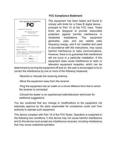
DECLARATION OF CONFORMITY This equipment has been tested and found to
Per FCC Part 2 Section 2. 1077(a)
comply with limits for a Class B digital device , pursuant to Part 15 of the FCC rules. These
Responsible Party Name: G.B.T. INC.
Address: 18305 Valley Blvd., Suite#A limits are designed to provide reasonable
LA Puent, CA 91744
protection against harmful interference in
Phone/Fax No: (818) 854-9338/ (818) 854-9339
hereby declares that the product residential installations. This equipment
Product Name: Mother Board
Model Number: GA-7VM generates, uses, and can radiate radio
Conforms to the following specifications: frequency energy, and if not installed and used FCC Part 15, Subpart B, Section 15.107(a) and Section 15.109(a), Class B Digital Device in accordance with the instructions, may cause Supplementary Information: This device complies with part 15 of the FCC Rules. Operation is subject to the harmful interference to radio communications. following two conditions: (1) This device may not cause harmful and (2) this device must accept any inference received, including that may cause undesired operation.
However, there is no guarantee that interference
Representative Person's Name: ERIC LU
Signature: Eric Lu will not occur in a particular installation. If this
Date: Mar. 3, 2000 equipment does cause interference to radio or
television equipment reception, which can be
determined by turning the equipment off and on, the user is encouraged to try to correct the interference by one or more of the following measures:
-Reorient or relocate the receiving antenna
-Move the equipment away from the receiver
-Plug the equipment into an outlet on a circuit different from that to which the receiver is connected
-Consult the dealer or an experienced radio/television technician for additional suggestions
You are cautioned that any change or modifications to the equipment not expressly approve by the party responsible for compliance could void Your authority to operate such equipment.
This device complies with Part 15 of the FCC Rules. Operation is subjected to the following two conditions 1) this device may not cause harmful interference and 2) this device must accept any interference received, including interference that may cause undesired operation.
Page Summary Contents For User's Manual for the 7VM AMD Athlon AGP Motherboard
Manual Details
| Brand | AMD |
|---|---|
| Pages | 73 |
| File Size | 1.01 MB |
| Published | May 14, 2026 |
Enter the captcha to get the download link:

Frequently Asked Questions
Does this motherboard comply with certain safety and interference standards?
Yes, it complies with both FCC Part 15 (Class B Digital Device) rules for radio interference and EN/IEC directives like LVD and EMC standards.
What steps should I take if my equipment causes radio interference?
Try reorienting the receiving antenna, moving the equipment away from the receiver, or plugging it into a different circuit outlet.
Is there any risk of physical damage when installing accessories?
Yes, use an inverse AMR card (Figure A) to avoid mechanical problems; do not use the non-inverse type (Figure B).
What does 'AMR' stand for in this manual?
AMR stands for Audio Modem Riser.