# A B C D E F G H I J K L M N O P Q R S T U V W X Y Z

7IX AMD Athlon AGP Motherboard USER'S MANUAL

Summary

This documentation provides comprehensive regulatory compliance details for your electronic hardware, including FCC Part 15 and CE Marking conformity declarations. It verifies that the device meets stringent international safety (LVD) and electromagnetic compatibility standards (EMC). The manual also includes detailed technical specifications, operational guides, and an extensive glossary of BIOS utilities and acronyms. Designed for advanced builders, engineers, and technicians who require assurance of compliance and deep system configuration knowledge.
📄 Preview PAGE OF 68

Page 1 Text Content

FCC Compliance Statement:

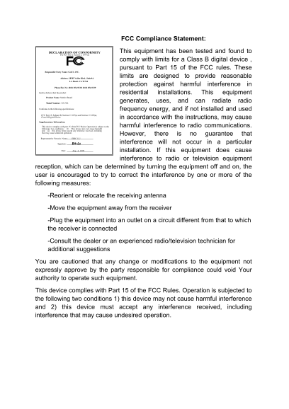
DECLARATION OF CONFORMITY This equipment has been tested and found to

Per FCC Part 2 Section 2. 1077(a)

comply with limits for a Class B digital device , pursuant to Part 15 of the FCC rules. These

Responsible Party Name: G.B.T. INC.

Address: 18305 Valley Blvd., Suite#A limits are designed to provide reasonable

LA Puent, CA 91744

protection against harmful interference in

Phone/Fax No: (818) 854-9338/ (818) 854-9339

hereby declares that the product residential installations. This equipment Product Name: Mother Board

Model Number: GA-7IX generates, uses, and can radiate radio

Conforms to the following specifications: frequency energy, and if not installed and used FCC Part 15, Subpart B, Section 15.107(a) and Section 15.109(a), Class B Digital Device in accordance with the instructions, may cause Supplementary Information: This device complies with part 15 of the FCC Rules. Operation is subject to the harmful interference to radio communications. following two conditions: (1) This device may not cause harmful and (2) this device must accept any inference received, including that may cause undesired operation.

However, there is no guarantee that

Representative Person's Name: ERIC LU

Signature: Eric Lu interference will not occur in a particular

Date: Aug. 4, 1999 installation. If this equipment does cause

interference to radio or television equipment

reception, which can be determined by turning the equipment off and on, the user is encouraged to try to correct the interference by one or more of the following measures:

-Reorient or relocate the receiving antenna

-Move the equipment away from the receiver

-Plug the equipment into an outlet on a circuit different from that to which the receiver is connected

-Consult the dealer or an experienced radio/television technician for additional suggestions

You are cautioned that any change or modifications to the equipment not expressly approve by the party responsible for compliance could void Your authority to operate such equipment.

This device complies with Part 15 of the FCC Rules. Operation is subjected to the following two conditions 1) this device may not cause harmful interference and 2) this device must accept any interference received, including interference that may cause undesired operation.

Page Summary Contents For 7IX AMD Athlon AGP Motherboard USER'S MANUAL

Page 1 FCC Compliance Statement: DECLARATION OF CONFORMITY This equipment has been tested and found to Per FCC Part 2 Section 2. 1077(a) comply with limits for a Class B digital device , pursuant to Part 15 ...
Page 2 Declaration of Conformity We, Manufacturer/Importer (full address) G.B.T. Technology Träding GMb H Ausschlager Weg 41, 1F, 20537 Hamburg, Germany declare that the product ( description of the apparatu...
Page 3 AMDTM Athlon AGP Motherboard USER'S MANUAL AMDTM Athlon Processor MAINBOARD REV. 1.0 First Edition
Page 5 TABLE OF CONTENT Revision History P.1 Item Checklist P.2 Summary of Features P.3 7IX Motherboard Layout P.5 Page index for Connectors / Panel and Jumper Definition P.6 Performance List P.18 Block diag...
Page 7 How this manual is organized This manual is divided into the following sections: 1) Revision List Manual revision information 2) Item Checklist Product item list 3) Features Product information & ...
Page 9 7IX Motherboard Revision History Revision Revision Note Date 1.01 Initial release of the 7IX motherboard user’s manual. Aug.1999 The author assumes no responsibility for any errors or omissions that m...
Page 10 Item Checklist Item Checklist þThe 7IX Motherboard þCable for IDE / Floppy device þDiskettes or CD (TUCD) for motherboard utilities o Internal COM2 Cable (Optional for VGA/AGP on-board Motherboard) o ...
Page 11 7IX Motherboard Summary Of Features Form factor Ÿ 30.5 cm x 20.7 cm ATX SIZE form factor, 4 layers PCB. CPU Ÿ AMD Athlon(K7) Slot A Processor Ÿ 512 KB 2nd cache in CPU Module Ÿ Supports 500MHz ~ 1GHz ...
Page 12 Summary Of Features Ÿ PS/2 Keyboard interface and PS/2 Mouse PS/2 Connector interface BIOS Ÿ Licensed AWARD BIOS, 2M bit FLASH RAM Additional Features Ÿ Internal/External Modem Wake up Ÿ Keyboard Pa...
Page 13 7IX Motherboard 7IX Motherboard Layout JP10 USB AMD751 PCI3 BZ1 JP9 AMD756
Page 14 7IX Motherboard Layout
Page 15 7IX Motherboard Page index for Connectors / Panel and Jumper Definition Connectors P.7 COMA / COMB / LPT Port P.7 USB Connector P.7 PS/2 Keyboard & PS/2 Mouse Connector P.8 PWR FAN P.8 CPU FAN / S...
Page 17 7IX Motherboard Connectors COM A / COM B / LPT Port LPT PORT COM A COM B USB Connector Pin No. Definition USB V0 USB D0- USB D0+ GND USB V1 USB D1- USB D1+ GND
Page 18 Connectors PS/2 Keyboard & PS/2 Mouse Connector PS/2 Mouse PS/2 Mouse/ Keyboard Pin No. Definition Data NC GND VCC(+5V) Clock NCPS/2 Keyboard POWER FAN Pin No. Definition GND +12V SENSE
Page 19 7IX Motherboard CPU FAN Pin No. Definition GND +12V SENSE SYSTEM FAN Pin No. Definition GND +12V SENSE
Page 20 Connectors ATX PWR Pin No. Definition 3,5,7,13,15-17 GND 1,2,11 3.3V 4,6,19,20 VCC +12V -12V -5V Power Good 5V SB stand by+5V PS-ON(Soft On/Off) FLOPPY RED LINE
Page 21 7IX Motherboard IDE1(Primary) , IDE2 (Secondary) RED LINE IDE 1 IDE 2 USB : USB Port Pin No. Definition VCC USB D0− USB D0+ GND VCC USB D1− USB D1+ GND
Page 22 Connectors IR : Infrared Connector (Optional) Pin No. Definition IR Data Output GND IR Data Input NC POWER (+)
Page 23 7IX Motherboard Panel and Jumper Definition J22 : For 2X11 PINs Jumper GN (Green Switch) Open: Normal Operation Close: Entering Green Mode GD (Green LED) Pin 1: LED anode(+) Pin 2: LED cathode(−) HD (...
Page 24 Panel and Jumper Definition JP10 : Keyboard Power On Pin No. Definition 1-2 close Keyboard Power on Enabled 2-3 close Keyboard Power on Disabled (Default) JP1 : CASE OPEN Pin No. Definition Signal GND
Page 25 7IX Motherboard JP3 : CLEAR CMOS Function Pin No. Definition 1-2 close Clear CMOS (User had to short 1-2 till boot) 2-3 close Normal (Default) JP9 : RING PWR ON (Internal Modem Card Wake Up) Pin No. D...
Page 26 Panel and Jumper Definition JP4 : Wake on LAN Pin No. Definition +5VSB GND Signal JP5 : Internal Buzzer Connector (Optional) Pin No. Definition Close On board speaker Enabled Open On board speaker Dis...
Page 27 7IX Motherboard BAT1 : Battery + Danger of explosion if battery is incorrectly replaced. + Replace only with the same or equivalent type recommended by the manufacturer. + Dispose of used batteries ac...
Page 28 Panel and Jumper Definition
Page 30 Performance List Performance List The following performance data list is the testing results of some popular benchmark testing programs. These data are just referred by users, and there is no responsi...
Page 31 7IX Motherboard Block Diagram 14.318MHz SLOT A 3.3V SDRAM DIMM Sockets Host Bus 100 MHz 100 MHz AMD 33MHz AGP Bus 66MHz 100 MHz 66MHz ICS 33 MHz 9248-64/9179-06 PCI Bus 33 MHz 48MHz 14.318MHz IDE Bus ...
Page 32 Memory Installation Memory Installation The motherboard has 3 dual inline memory module (DIMM) sockets. The BIOS will automatically detects memory type and size. To install the memory module, just pus...
Page 33 7IX Motherboard $ Page index for BIOS Setup Page The MAIN MENU P.23 Standard CMOS Features P.26 Advanced BIOS Features P.30 Advanced Chipset Features P.34 Integrated Peripherals P.38 Power Management ...
Page 34 BIOS Setup BIOS Setup BIOS Setup is an overview of the BIOS Setup Program. The program that allows users to modify the basic system configuration. This type of information is stored in battery-backed ...
Page 35 7IX Motherboard GETTING HELP Main Menu The on-line description of the highlighted setup function is displayed at the bottom of the screen. Status Page Setup Menu / Option Page Setup Menu Press F1 to p...
Page 36 BIOS Setup Standard CMOS Features This setup page includes all the items in standard compatible BIOS. Advanced BIOS Features This setup page includes all the items of Award special enhanced features. ...
Page 37 7IX Motherboard Save & Exit Setup Save CMOS value settings to CMOS and exit setup. Exit Without Saving Abandon all CMOS value changes and exit setup.
Page 38 BIOS Setup Standard CMOS Features The items in Standard CMOS Setup Menu (Figure 2) are divided into 9 categories. Each category includes no, one or more than one setup items. Use the arrows to highlig...
Page 39 7IX Motherboard Time The times format in <hour> <minute> <second>. The time is calculated base on the 24- hour military-time clock. For example, 1 p.m. is 13:00:00. IDE Primary Maste...
Page 40 BIOS Setup Floppy 3 Mode Support (for Japan Area) Disabled Normal Floppy Drive. Drive A Drive A is 3 mode Floppy Drive. Drive B Drive B is 3 mode Floppy Drive. Both Drive A & B are 3 mode Floppy D...

Manual Details

Brand AMD
Pages 68
File Size 1.28 MB
Published May 14, 2026
173 views

Enter the captcha to get the download link:

captcha

Frequently Asked Questions

How do I reset my BIOS settings or exit the setup utility?

To quit without saving changes, select ESC:Quit. To save and exit, press F10:Save & Exit Setup.

What steps should I take if this device causes radio interference?

Try moving the equipment from the receiver's location, or plug it into an outlet on a different circuit.

According to the BIOS appendix, what does 'DMI' stand for?

DMI stands for Desktop System Management Interface.