# A B C D E F G H I J K L M N O P Q R S T U V W X Y Z

Texas Instruments - TPS62050, TPS62051, TPS62052, TPS62054, TPS62056 Data Handbook

Summary

The TPS6205x family comprises high-efficiency synchronous step-down DC/DC converters delivering up to 800mA output current. Operating from 2.7V to 10V input, they achieve up to 95% efficiency with only 12µA quiescent current. Features include adjustable output (0.7V-6V), fixed voltage options (1.5V, 1.8V, 3.3V), external clock synchronization up to 1.2MHz, 100% maximum duty cycle, internal soft-start, and comprehensive protection. The MSOP-10 package suits space-constrained designs. Target users are designers of portable electronics including cellular phones, PDAs, handheld PCs, and low-power DSP supplies requiring efficient power management.
📄 Preview 📖 Table of Contents Contents PAGE OF 23

Page 1 Text Content

TPS62050, TPS62051

www.ti.com TPS62052, TPS62054, TPS62056 SLVS432D–SEPTEMBER 2002–REVISED OCTOBER

800-m A SYNCHRONOUS STEP-DOWN CONVERTER

FEATURES DESCRIPTION High-Efficiency Synchronous Step-Down The TPS6205x devices are family of high-efficiency Converter With up to 95% Efficiency synchronous step-down dc/dc converters ideally suited 12-µA Quiescent Current (Typ) for systems powered from 1-cell or 2-cell Li-Ion

2.7-V to 10-V Operating Input Voltage Range battery or from 3-cell to 5-cell Ni Cd, Ni MH, or alkaline• battery.•

Adjustable Output Voltage Range From 0.7 to The TPS62050 is synchronous PWM converter with

Fixed Output Voltage Options Available in integrated N-channel and P-channel power MOSFET• V, 1.8 V, and 3.3 switches. Synchronous rectification increases ef-1.5 ficiency and reduces external component count. To•

Synchronizable to External Clock Signal up to

achieve highest efficiency over wide load current1.2

range, the converter enters power-saving•

High Efficiency Over Wide Load Current

pulse-frequency modulation (PFM) mode at light load

Range in Power-Save Mode

currents. Operating frequency is typically k Hz,

100% Maximum Duty Cycle for Lowest

allowing the use of small inductor and capacitor values.

Dropout

The device can be synchronized to an external clock

Low Noise Operation in Forced Fixed signal in the range of k Hz to 1.2 MHz. For low noise Frequency PWM Operation Mode operation, the converter can be programmed into

Internal Softstart forced-fixed frequency in PWM mode. In shutdown• mode, the current consumption is reduced to less than•

Overtemperature and Overcurrent Protected

µA. The TPS6205x is available in the 10-pin (DGS)

Available in 10-Pin Microsmall Outline

micro-small outline package (MSOP) and operates

Package MSOP ff ic ie cy

over an free air temperature range of -40°C to 85°C.

APPLICATIONS Cellular Phones Organizers, PDAs, and Handheld PCs Low Power DSP Supply Digital Cameras and Hard Disks

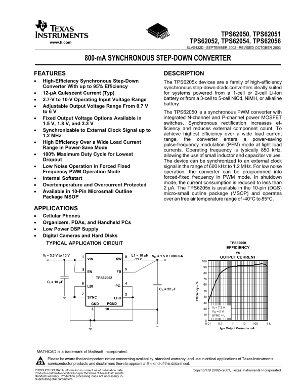
TYPICAL APPLICATION CIRCUIT TPS62050 EFFICIENCY vs

VO = 1.5 V / 800 m AL1 = 10 µHVI = 3.3 V to 10 V

OUTPUT CURRENT

VIN SW

EN FB

TPS62052

Ci = 10 µF

LBI PG

Co = 22 µF

SYNC LBO

GND PGND

VI = 7.2 V, VO = 5 V, SYNC = L

IO – Output Current – m A

MATHCAD is trademark of Mathsoft Incorporated. Please be aware that an important notice concerning availability, standard warranty, and use in critical applications of Texas Instruments semiconductor products and disclaimers thereto appears at the end of this data sheet. PRODUCTION DATA information is current as of publication date. Copyright 2002–2003, Texas Instruments Incorporated Products conform to specifications per the terms of Texas Instruments standard warranty. Production processing does not necessarily in- cludetestingofallparameters.

Page Summary Contents For Texas Instruments - TPS62050, TPS62051, TPS62052, TPS62054, TPS62056 Data Handbook

Page 1 TPS62050, TPS62051 www.ti.com TPS62052, TPS62054, TPS62056 SLVS432D–SEPTEMBER 2002–REVISED OCTOBER 800-m A SYNCHRONOUS STEP-DOWN CONVERTER FEATURES DESCRIPTION High-Efficiency Synchronous Step-Down Th...
Page 2 TPS62050, TPS62051 TPS62052, TPS62054, TPS62056 www.ti.com SLVS432D–SEPTEMBER 2002–REVISED OCTOBER This integrated circuit can be damaged by ESD. Texas Instruments recommends that all integrated circu...
Page 3 TPS62050, TPS62051 TPS62052, TPS62054, TPS62056 www.ti.com SLVS432D–SEPTEMBER 2002–REVISED OCTOBER ELECTRICAL CHARACTERISTICS VI =7.2 V, VO 3.3 V, IO m A, EN VI, TA =-40°C to 85°C unless otherwise not...
Page 4 TPS62050, TPS62051 TPS62052, TPS62054, TPS62056 www.ti.com SLVS432D–SEPTEMBER 2002–REVISED OCTOBER ELECTRICAL CHARACTERISTICS (continued) VI =7.2 V, VO 3.3 V, IO m A, EN VI, TA =-40°C to 85°C unless o...
Page 5 TPS62050, TPS62051 TPS62052, TPS62054, TPS62056 www.ti.com SLVS432D–SEPTEMBER 2002–REVISED OCTOBER PIN ASSIGNMENTS DGS PACKAGE (TOP VIEW) VIN PGND LBO SW GND EN PG SYNC FB LBI Terminal Functions TERMI...
Page 6 TPS62050, TPS62051 TPS62052, TPS62054, TPS62056 www.ti.com SLVS432D–SEPTEMBER 2002–REVISED OCTOBER FUNCTIONAL BLOCK DIAGRAM Current Limit Comparator Undervoltage Lockout REF Bias Supply Soft Start I(A...
Page 7 TPS62050, TPS62051 TPS62052, TPS62054, TPS62056 www.ti.com SLVS432D–SEPTEMBER 2002–REVISED OCTOBER PARAMETER MEASUREMENT INFORMATION All graphs were generated using the circuit as shown unless otherwi...
Page 8 TPS62050, TPS62051 TPS62052, TPS62054, TPS62056 www.ti.com SLVS432D–SEPTEMBER 2002–REVISED OCTOBER ff ic ie cy ff ic ie cy TYPICAL CHARACTERISTICS TABLE OF GRAPHS FIGURE Efficiency vs load current Swi...
Page 9 TPS62050, TPS62051 TPS62052, TPS62054, TPS62056 www.ti.com SLVS432D–SEPTEMBER 2002–REVISED OCTOBER ff ic ie cy /d iv /d iv /d iv TYPICAL CHARACTERISTICS (continued) TPS62054 TPS62056 EFFICIENCY EFFICI...
Page 10 TPS62050, TPS62051 TPS62052, TPS62054, TPS62056 www.ti.com SLVS432D–SEPTEMBER 2002–REVISED OCTOBER APPLICATION INFORMATION Operation The TPS6205x is synchronous step-down converter that operates with ...
Page 11 TPS62050, TPS62051 TPS62052, TPS62054, TPS62056 www.ti.com SLVS432D–SEPTEMBER 2002–REVISED OCTOBER APPLICATION INFORMATION (continued) Feedforward Capacitor The feedforward capacitor, C(ff) shown in F...
Page 12 TPS62050, TPS62051 TPS62052, TPS62054, TPS62056 www.ti.com SLVS432D–SEPTEMBER 2002–REVISED OCTOBER APPLICATION INFORMATION (continued) VI(min) VO(max) IO(max) r DS(on)(max) RL IO(max) = Maximum output...
Page 13 TPS62050, TPS62051 TPS62052, TPS62054, TPS62056 www.ti.com SLVS432D–SEPTEMBER 2002–REVISED OCTOBER APPLICATION INFORMATION (continued) Undervoltage Lockout The undervoltage lockout circuit prevents th...
Page 14 TPS62050, TPS62051 TPS62052, TPS62054, TPS62056 www.ti.com SLVS432D–SEPTEMBER 2002–REVISED OCTOBER APPLICATION INFORMATION (continued) ENABLE/Low-Battery Detector (Enhanced Version) TPS62051 Only The ...
Page 15 TPS62050, TPS62051 TPS62052, TPS62054, TPS62056 www.ti.com SLVS432D–SEPTEMBER 2002–REVISED OCTOBER APPLICATION INFORMATION (continued) No Load Operation If the converter operates in the forced PWM mod...
Page 16 TPS62050, TPS62051 TPS62052, TPS62054, TPS62056 www.ti.com SLVS432D–SEPTEMBER 2002–REVISED OCTOBER APPLICATION INFORMATION (continued) STANDARD CIRCUIT FOR FIXED VOLTAGE VERSION L1 = 10 µH VO = 1.8 V ...
Page 17 TPS62050, TPS62051 TPS62052, TPS62054, TPS62056 www.ti.com SLVS432D–SEPTEMBER 2002–REVISED OCTOBER APPLICATION INFORMATION (continued) INDUCTOR SELECTION 10-µH minimum inductor should be used with the...
Page 18 TPS62050, TPS62051 TPS62052, TPS62054, TPS62056 www.ti.com SLVS432D–SEPTEMBER 2002–REVISED OCTOBER APPLICATION INFORMATION (continued) OUTPUT CAPACITOR SELECTION The output capacitor should have minim...
Page 19 TPS62050, TPS62051 TPS62052, TPS62054, TPS62056 www.ti.com SLVS432D–SEPTEMBER 2002–REVISED OCTOBER APPLICATION INFORMATION (continued) Table 4. Capacitor Manufacturers MANUFACTURER CAPACITOR TYPE INTE...
Page 20 PACKAGE OPTION ADDENDUM www.ti.com 8-Aug-2005 PACKAGING INFORMATION Orderable Device Status Package Package Pins Package Eco Plan Lead/Ball Finish MSL Peak Temp Type Drawing Qty TPS62050DGS ACTIVE MSO...
Page 21 PACKAGE OPTION ADDENDUM www.ti.com 8-Aug-2005 at high temperatures, TI Pb-Free products are suitable for use in specified lead-free processes. Green (Ro HS no Sb/Br): TI defines "Green" to m...
Page 23 IMPORTANT NOTICE Texas Instruments Incorporated and its subsidiaries (TI) reserve the right to make corrections, modifications, enhancements, improvements, and other changes to its products and servic...

Manual Details

Brand Texas Instruments
Pages 23
File Size 444.81 KB
Published June 16, 2026
1 views

Enter the captcha to get the download link:

captcha

Frequently Asked Questions

What is the input voltage range?

It has an operating input voltage range of 2.7 V to 10 V.

What is the maximum output current?

The devices have an 850 mA output current rating.

Are there fixed output voltage options?

Yes, there are fixed options of 1.5 V, 1.8 V, and 3.3 V.

What is the typical operating frequency?

The typical operating frequency is 850 kHz.

What is the typical quiescent current?

The typical quiescent current is 12 µA.