Texas Instruments - TL1454A, TL1454AY Dual-Channel Pulse-WIDTH-Modulation (PWM) Control Circuit Data Manual
Summary
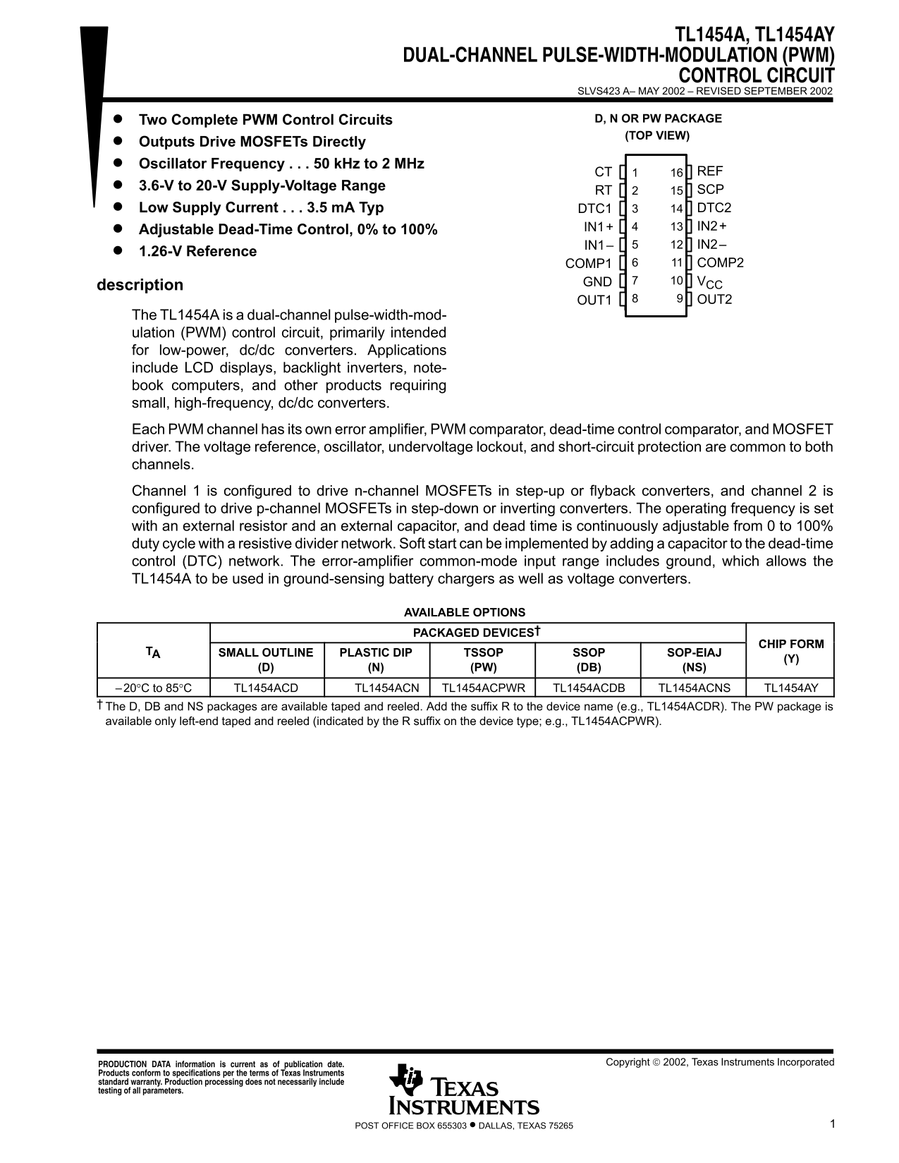
The TL1454A/AY is a dual-channel PWM control circuit designed for efficient low-power DC/DC conversion in demanding electronics. It is ideal for creating backlights, LCD displays, and portable computing power supplies requiring high-frequency conversion. This manual details the powerful functional block diagram, covering error amplifier theory, customizable PWM timing (including adjustable dead-time), and robust features like undervoltage lockout. Use this guide to integrate precise, stable voltage regulation into your next project.
Manual Details
| Brand | Texas Instruments |
|---|---|
| Pages | 30 |
| File Size | 584.19 KB |
| Published | June 22, 2026 |
Enter the captcha to get the download link:

Frequently Asked Questions
How are the operating frequency and voltage regulated?
The operating frequency is set using an external resistor and capacitor; the device handles a supply voltage range of 3.6 V to 20 V.
What type of converters can this dual-channel circuit drive?
Channel 1 drives n-channel MOSFETs for step-up/flyback, while Channel 2 drives p-channel MOSFETs for step-down or inverting converters.
Is dead time control configurable?
Yes, dead time is continuously adjustable from 0% to 100% duty cycle using a resistive divider network.
What precautions must be taken when using this IC?
The product is not intended for military or automotive use unless specifically designated by us, and buyers are solely responsible for compliance with all legal requirements.