Page 1
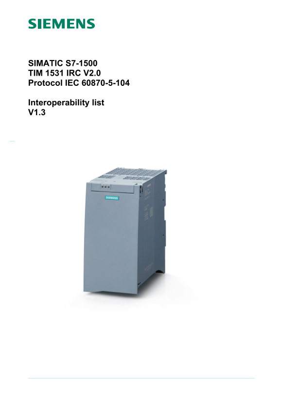
SIMATIC S7-1500 TIM 1531 IRC V2.0 Protocol IEC 60870-5-104 Interoperability list V1.3
Page 2
Page 2 of 19 1 VERSION HISTORY Version Date Author Review Remarks 1.0 08.02.2018 Joerg First draft 1.1 08.22.2018 Joerg Release before conformance test 1.2 11.05.2018 Joerg Release after conformance t...
Page 3
2 SCOPE OF THIS DOCUMENT The scope of this document is to describe in a detailed way the implementation of the IEC 60870-5 communication interface as indicated in the first page. It contains a default...
Page 4
Page 4 of 19 System definition Controlling station definition (Master) Controlled station definition (Slave) X 4.2 Network configuration (network-specific parameter, all configurations that are used a...
Page 5
Page 5 of 19 4.3 Physical layer (network-specific parameter, all interfaces and data rates that are used are to be marked ‘X’) Transmission speed (control direction) Unbalanced interchange Unbalanced ...
Page 6
Page 6 of 19 4.4 Link layer (network-specific parameter, all options that are used are to be marked ‘X’. Specify the maximum frame length. If a non-standard assignment of class 2 messages is implement...
Page 7
Page 7 of 19 4.5 Application layer Transmission mode for application data Mode 1 (Least significant octet first), as defined in clause 4.10 of IEC 60870-5-4, is used exclusively in this companion stan...
Page 8
Page 8 of 19 Selection of standard ASDUs Process information in monitor direction (station-specific parameter, mark each Type ID ‘X’ if it is only used in the standard direction, ‘R’ if only used in t...
Page 9
Page 9 of 19 Process information in control direction (station-specific parameter, mark each Type ID ‘X’ if it is only used in the standard direction, ‘R’ if only used in the reverse direction, and ‘B...
Page 10
Page 10 of 19 Parameter in control direction (station-specific parameter, mark each Type ID ‘X’ if it is only used in the standard direction, ‘R’ if only used in the rever Xse direction, and ‘B’ if us...
Page 11
Page 11 of 19 Type Identification Cause of transmission 1 2 3 4 5 6 7 8 9 10 11 12 13 20 44 45 46 47 to to <1> M_SP_NA_1 X X <2> M_SP_TA_1 <3> M_DP_NA_1 X X <4> M_DP_TA_1 <5...
Page 12
Page 12 of 19 Type Identification Cause of transmission 1 2 3 4 5 6 7 8 9 10 11 12 13 20 44 45 46 47 to to <50> C_SE_NC_1 X X X X X X X X X <51> C_BO_NA_1 X X X X X X X <58> C_SC_TA_...
Page 13
Page 13 of 19 Basic application functions Station initialization (station-specific parameter, mark ‘X’ if function is used) Remote initialization Only QRP=… supported Only COI=… supported Cyclic data ...
Page 14
Page 14 of 19 Station interrogation (station-specific parameter, mark ‘X’ if function is only used in the standard direction, ‘R’ if only used in the reverse direction, and ‘B’ if used in both directi...
Page 15
Page 15 of 19 Transmission of integrated totals (station- or object-specific parameter, mark ‘X’ if function is only used in the standard direction, ‘R’ if only used in the reverse direction, and ‘B’ ...
Page 16
Page 16 of 19 Test procedure (station-specific parameter, mark ‘X’ if function is only used in the standard direction, ‘R’ if only used in the reverse direction, and ‘B’ if used in both directions) Te...
Page 17
Page 17 of 19 Definition of time outs Parameter Default value Remarks Selected value t0 30[s] Time out of connection establishment 30 s t1 15[s] Time out of send or test APDUs 15 s t2 10[s] Time out f...
Page 18
Page 18 of 19 Serial X.21 interface Other selection from RFC 2200: GPRS List of valid documents from RFC 2200 7. etc.
Page 19
5 ADDITIONAL INFORMATION Value range of Integrated totals is 0 - 0x7FFF FFFF, because only the positive part will be processed.