SHARP PC817 Series Data Sheet
Summary
The PC817 Series offers reliable signal isolation using high-performance photocouplers to link circuits with differing voltages and impedances. Available in multiple channel configurations (1–4), these components provide vital electrical separation (up to 5000V) for applications ranging from computer terminals and industrial controllers to automated machines and home appliances. This technical manual serves as a comprehensive guide for engineers, detailing all electro-optical characteristics, absolute maximum ratings, and performance curves necessary for reliable system design and integration.
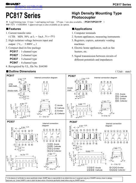
Page 1 Text Content
PC817 Series
查询PC-817供应商 0. 5T 0. 0. 3. 3. no de ar 0. 5T
High Density Mounting Type 0. 0. 3. 3.
PC817 Series Photocoupler Lead forming type ( I type and taping reel type ( P type are also available. (PC817I/PC817P ❈❈ TUV ( VDE0884 approved type is also available as an option.
Features Applications 1. Current transfer ratio 1. Computer terminals
2. 0. CTR: MIN. 50% at I 5m A 6. ,VCE=5V) 2. System appliances, measuring instruments
2. High isolation voltage between input and 3. Registers, copiers, automatic vending
output ( Viso 5 000V rms machines
3. Compact dual-in-line package 4. Electric home appliances, such as fan
PC817 1-channel type heaters, etc.
PC827 2-channel type
5. Signal transmission between circuits of
PC837 3-channel type
different potentials and impedances
PC847 4-channel type 4. Recognized by UL, file No. E64380
0. 5T no de ar
0. 0. Outline Dimensions 3. 3. Unit mm)
PC817 PC827
Internal connection diagram Internal connection diagram
CTR rank mark
Anode
0. 0. Anode mark mark 2. 6.
Anode
0.2 Cathode 0.9 0.3
0.3 Emitter 1.2 0.
6. 0.3 7.62 0.3 Collector
Anode Cathode 0.1
Emitter θθ Collector
0.1 0.1 θ= 0 to 13
0.5 0 to 13 0.5
PC837 PC847
Internal connection Internal connection
diagram 0.25 diagram 2.54
Anode Cathode 0.2
Emitter 0.3
1.2 Collector 0.5
0.1 0 to 13 0.5
0.1 Anode Emitter
0 to 13
Cathode Collector
In the absence of confirmation by device specification sheets, SHARP takes no responsibility for any defects that occur in equipment using any of SHARP's devices, shown in catalogs, data books, etc. Contact SHARP in order to obtain the latest version of the device specification sheets before using any SHARP's device.”
Page Summary Contents For SHARP PC817 Series Data Sheet
Manual Details
| Brand | Sharp |
|---|---|
| Pages | 4 |
| File Size | 60.41 KB |
| Published | June 02, 2026 |
Enter the captcha to get the download link:
