Roland TD-27KV Electronic Drum Kit Setup Guide - User Manual
Summary
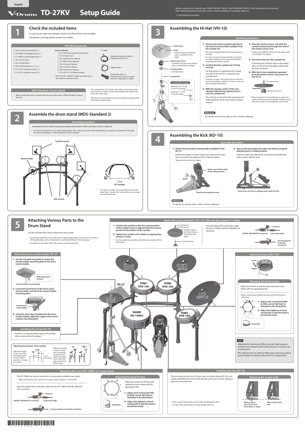
This comprehensive setup guide provides detailed instructions for assembling and connecting your Roland TD-27KV professional digital drum set system. It covers everything from mounting various pads (snare, toms, cymbals) and kick pedal to safely installing and adjusting specialized components like the hi-hat stand. Designed for musicians who require accurate and stable setup, this manual ensures you can properly assemble all parts and understand safe operational practices for optimal performance.
Page 1 Text Content
Before using this unit, carefully read “USING THE UNIT SAFELY” and “IMPORTANT NOTES” of this document and accessories. After reading, keep the document(s) where it will be available for immediate reference.
TD-27KV Setup Guide
© 2020 Roland Corporation
Check the included items Assembling the Hi-Hat (VH-10) As soon as you open the package, check to see that all items are included. If anything is missing, please contact your dealer.
Assembly procedure
1. Remove the clutch included with the hi- 4. Place the motion sensor unit with the
TD-27KV (Drum Set) Clutch Screw
hat stand (commercially available) from cymbal rod passing through the hole of the cymbal rod. the motion sensor unit.
TD-27 (Drum sound module) x 1 Owner’s Manuals Cables Hi-Hat
* The clutch included with the hi-hat stand will not * Position the CONTROL OUT jack on the farther side,
TD-27KV Setup Guide (this document) * “Roland” logo on the farther
PD-140DS (V-Pad digital snare) x 1
be used. as viewed from the player.
side, as viewed from the
TD-27 Quick Start Dedicated connection cable x 1
CY-18DR (V-Cymbal digital ride) x 1 player * It is not necessary to remove the felt component
PD-140DS Owner’s Manual (Packed with the TD-27)
(or rubber portion) on the hi-hat stand used for 5. Pass the hi-hat over the cymbal rod.
VH-10 (V-Hi-hat) x 1
CY-18DR Owner’s Manual Motion Sensor Unit supporting the bottom cymbal.
KD-10 (Kick Pad) x1 * CONTROL OUT jack on the farther Positioning the “Roland” logo on the farther
VH-10 Owner’s Manual
side, as viewed from the player 2. Confirm that the cymbal rod is firmly
PDX-100 (V-Pad) (tom1, 2, 3) x 3 side, as viewed from the player will provide
KD-10 Owner’s Manual Trigger cable x 1
secured.
the best sensitivity.
CY-12C (V-Cymbal for crash 1) x 1 Insulating Plate
PDX-100 Owner’s Manual
* Sponge side up For instructions on tightening the cymbal
CY-13R (V-Cymbal for crash 2) x 1 CY-13R / CY-12C Owner’s Manual 6. With the hi-hat completely separated
rod, refer to the owner’s manual for your
Connection cable x 2 from the motion sensor unit, power-on
* The TD-27/PD-140DS/CY-18DR accessories are in (Packed in the respective cartons Cymbal Rod cymbal stand.
the TD-27.
the respective packing cartons. of the PD-140DS and CY-18DR)
* Looseness or play in the cymbal rod can make the top hi-hat unstable, causing it to shake or turn, and clutch screw
Compatible Stands
prevent proper functioning.
Diameter: 6.0–7.0 mm
(1/4 to 5/16 inches) Separated
* This package does not include a kick pedal, a hi-hat stand, and a 3. With the sponge surface of the anti-
MDS-Standard 2 (Drum Stand) motion sensor unit
snare stand. Use with a commercially available kick pedal, hi-hat vibration plate facing upward, pass it
Diameter: 11.7 mm
stand, and snare stand. (1/2 inches) Max. over the cymbal rod.
* When checking the items included with the drum stand, refer to “MDS-Standard 2 Owner’s
Manual.” This will rest on top of the felt component (or * When turning the VH-10 upside down, protect the
* The drum key used to attach the pads is inside the packing carton
rubber portion) of the hi-hat stand's cymbal clutch and the sensor from damage. Handle the unit
of the drum sound module.
with care so that it is not dropped or overturned.
receiver.
Reference
Assemble the drum stand (MDS-Standard 2)
For details on the hi-hat, refer to “VH-10 Owner’s Manual.”
Assembly procedure
Assemble the drum stand using the procedure described in “MDS-Standard 2 Owner’s Manual.” * This drum set illustration is for a right-handed player. If you want to set up for a left-handed player, assemble it as described in “Assembly for a left-handed player” in “MDS-Standard 2 Owner’s Manual.”
Assembling the Kick (KD-10)
Cymbal mounts
Assembly procedure
1. Attach the kick pedal (commercially available) to the 2. Step on the kick pedal and make sure that it’s properly KD-10. attached and in a stable position. Position the beater so that it strikes the center of the head, Check to make sure that the KD-10 and the kick pedal both then secure the kick pedal and KD-10 firmly in place. make contact with the floor.
Mount holder
* Take care not to pinch your fingers.
Beater must hit the center of the striking surface
Beater
1.2 m (47 inches)
* For reasons of safety, do not spread the drum stand
Check to be sure they’re making contact with the floor
wider than 1.2 meters (47 inches). Doing so can cause Install the kick pedal securely. the stand to fall over.
Pad mounts
Reference For details on the kick, refer to “KD-10 Owner’s Manual.”
Attaching Various Parts to the Attach the crash cymbal (CY-12C / CY-13R) and ride cymbal (CY-18DR)
1. Position the cymbal so that the convex portion Cymbal nut
Drum Stand Insert the plug of the connection cable
Protector
Felt washer
of the cymbal mount is aligned with the concave into the CY-18DR’s DIGITAL TRIGGER OUT
portion of the bottom of the cymbal. “Roland” logo on
connector.
the farther side, as
Use the included drum key to attach the various parts.
DIGITAL TRIGGER OUT connector Connection cable
2. Tighten the cymbal nut to obtain an appropriate viewed from the amount of sway. player
* The settings explained in this guide are for a right-handed player. If you want to set up for a left-handed player, refer to “Assembly for a Left-Handed Player” in the next page. * Use the cymbal nut and felt washer that are included with the
Use the protector
Convex portion
drum stand.
* For details on each part, refer to the owner’s manual of each part. to lock the connection.
Attach the drum sound module (TD-27) Attach the toms (PDX-100) 1. Use the included wing bolts to attach the
Loosen
sound module mounting plate to the drum sound module.
CRASH1 CRASH2
(CY-12C) (CY-13R) Tighten
Roland logo faces outward
Adjusting the head tension
Sound module mounting plate TOM1 TOM2
TD-27
(PDX-100) (PDX-100) Adjust the tension so that the pad responds to your
2. Loosen the hand knob of the drum stand strikes with the appropriate feel. mount holder, and insert the sound module mounting plate.
* Before using the pad, tighten the head so that the tension is (CY-18DR) rather firm.
HI-HAT (VH-10) 1. Adjust each tuning bolt little
by little, across the head as
Hand knob of
indicated in the illustration.
mount holder
2. Adjust the tightness of each
SNARE tuning bolt so that the head is
3. Using the drum key included with the drum
tensioned evenly.
(PD-140DS) (PDX-100)
sound module, adjust the angle of the sound module mounting plate.
KICK (KD-10) tuning bolt
Installing the hi-hat (VH-10) Position it so that the Roland logo on the farther side, as viewed from the player.
Adjusting the head tension affects only the head response,
Adjusting the position of the cymbal
OK and does not change the pitch of the sound as it would on an
Attach the cymbal
acoustic drum.
so that its center
Adjust the height
does not extend
Pitch adjustments are made by editing the sound in your drum
of the rod so that
toward the back
the highest point 1.2 m sound module. For details, refer to the “TD-27 Quick Start.”
beyond the pipes
of the cymbal is (47 inches)
of the stand (the
less than 1.2 meters
pipes at the back
(47 inches).
of the stand).
Mounting the snare (PD-140DS) on a snare stand Installing the kick (KD-10)
The PD-140DS can only be used with a commercially available snare stand. If you’re using this unit on a V-Drums mat, on a Noise Eater (NE-10), or on
Adjusting the head tension Adjusting the anchor bolts
carpet, extending the anchor bolts will secure the unit in place, making it
* Make sure that the snare stand you are using is able to support a 14-inch shell.
Adjust the tension so that the pad easier for you to perform.
responds to your strikes with the
Insert the plug of the connection cable into the PD-140DS’s DIGITAL TRIGGER appropriate feel. OUT connector.
1. Adjust each tuning bolt little
Protector
by little, across the head as indicated in the illustration.
DIGITAL TRIGGER OUT connector Connection cable
2. Adjust the tightness of each * When used on flooring, the anchor bolts may damage the floor.
When using on When using on the
tuning bolt so that the head is the V-Drums mat, floor
tuning bolt * The tips of the anchor bolts are sharp. Handle with care.
tensioned evenly. Noise Eater, or carpet
Use the protector to lock the connection.
Page Summary Contents For Roland TD-27KV Electronic Drum Kit Setup Guide - User Manual
Manual Details
| Brand | Roland |
|---|---|
| Pages | 2 |
| File Size | 3.86 MB |
| Published | May 27, 2026 |
Enter the captcha to get the download link:

Frequently Asked Questions
What safety precautions must be followed when using this unit?
An adult must supervise use around children, keep small items out of reach, and ensure stable placement to prevent injury or tipping.
What must I check if the top hi-hat is unstable or shaking?
Check the cymbal rod for looseness or play in the cymbal mount, as this can cause instability and disrupt function.
Are all stands included with this drum set package?
No; the package does not include a kick pedal, a hi-hat stand, or a snare stand. These must be used with commercially available options.