# A B C D E F G H I J K L M N O P Q R S T U V W X Y Z

ROHM - TECHNICAL NOTE Brush Motors H-Bridge Drivers (18V max.) BD6220, BD6221, BD6222, BD6225, BD6220, BD6221, BD6222, BD6225, BD6220, BD6221, BD6222, BD6225, BD622 - Owner's Manual / User Guide

Summary

These highly efficient H-bridge driver ICs provide full bridge motor control solutions for a wide range of applications. Operating across 3V to 36V, they feature robust PWM signal support and integrate critical safety circuits like Over-Current Protection and Under-Voltage Lockout. Ideal for engineers developing consumer electronics, including car multimedia systems, AV equipment, CD/DVD players, and peripheral devices. The manual details comprehensive technical specifications, operating guidelines, and application parameters necessary for precise circuit design integration.
📄 Preview PAGE OF 17

Page 1 Text Content

TECHNICAL NOTE

For brush motors

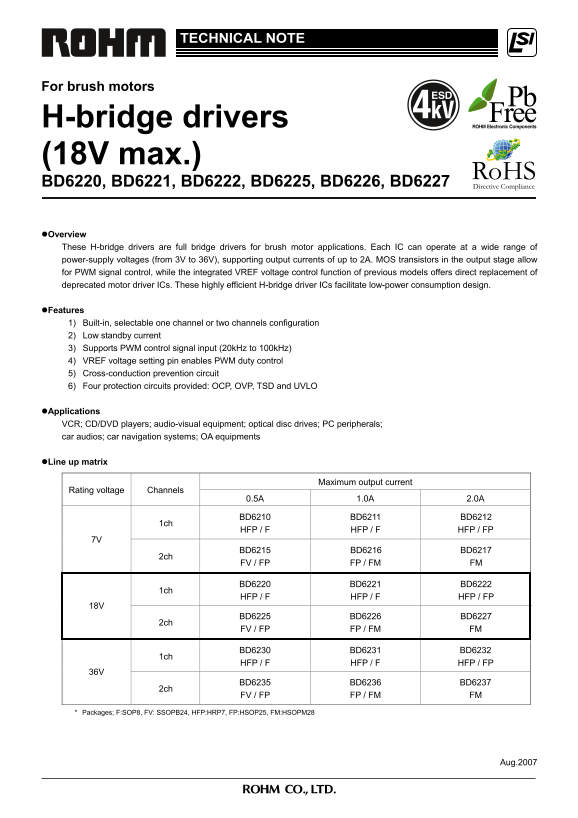
H-bridge drivers (18V max.) BD6220, BD6221, BD6222, BD6225, BD6226, BD6227 Overview These H-bridge drivers are full bridge drivers for brush motor applications. Each IC can operate at a wide range of power-supply voltages (from 3V to 36V), supporting output currents of up to 2A. MOS transistors in the output stage allow for PWM signal control, while the integrated VREF voltage control function of previous models offers direct replacement of deprecated motor driver ICs. These highly efficient H-bridge driver ICs facilitate low-power consumption design. Features 1) Built-in, selectable one channel or two channels configuration 2) Low standby current 3) Supports PWM control signal input (20k Hz to 100k Hz) 4) VREF voltage setting pin enables PWM duty control 5) Cross-conduction prevention circuit 6) Four protection circuits provided: OCP, OVP, TSD and UVLO

Applications VCR; CD/DVD players; audio-visual equipment; optical disc drives; PC peripherals; car audios; car navigation systems; OA equipments

Line up matrix

Maximum output current

Rating voltage Channels

BD6210 BD6211 BD6212

HFP / F HFP / F HFP / FP

BD6215 BD6216 BD6217

FV / FP FP / FM FM

BD6220 BD6221 BD6222

HFP / F HFP / F HFP / FP

BD6225 BD6226 BD6227

FV / FP FP / FM FM

BD6230 BD6231 BD6232

HFP / F HFP / F HFP / FP

BD6235 BD6236 BD6237

FV / FP FP / FM FM

* Packages; F:SOP8, FV: SSOPB24, HFP:HRP7, FP:HSOP25, FM:HSOPM28

Aug.2007

Page Summary Contents For ROHM - TECHNICAL NOTE Brush Motors H-Bridge Drivers (18V max.) BD6220, BD6221, BD6222, BD6225, BD6220, BD6221, BD6222, BD6225, BD6220, BD6221, BD6222, BD6225, BD622 - Owner's Manual / User Guide

Page 1 TECHNICAL NOTE For brush motors H-bridge drivers (18V max.) BD6220, BD6221, BD6222, BD6225, BD6226, BD6227 Overview These H-bridge drivers are full bridge drivers for brush motor applications. Each IC...
Page 2 Absolute maximum ratings (Ta=25°C) Parameter Symbol Ratings Unit Supply voltage VCC 18 V Output current IOMAX 0.5 *1 / 1.0 *2 / 2.0 *3 A All other input pins VIN -0.3 ~ VCC V Operating temperature TOP...
Page 3 Electrical characteristic curves (Reference data) In te rn al og ic : H /L sc ill at io Fr eq ue nc y: [k z] In pu t B ia ur re nt : I IH irc ui t C ur re nt : I cc [m Supply Voltage: Vcc [V] Supply V...
Page 4 Electrical characteristic curves (Reference data) – Continued ut pu t V ol ta ge : V [V ut pu t V ol ta ge : V [V ut pu t V ol ta ge :V -V [V ut pu t V ol ta ge : V -V [V Output Current: IOUT [A] Outp...
Page 5 Block diagram and pin configuration BD6220F / BD6221F 6 VREF DUTY PROTECT Table 1 BD6220/21F Pin Name Function 1 OUT1 Driver output 2 VCC Power supply 3 VCC Power supply 8 GND 7 1 4 FIN Control input ...
Page 6 Block diagram and pin configuration – Continued BD6222FP Table 3 BD6222FP 17 VREF DUTY PROTECT Pin Name Function 1,2 OUT1 Driver output 6 GND Small signal ground 7,8 RNF Power stage ground 12,13 OUT2 ...
Page 7 Block diagram and pin configuration – Continued BD6225FP, BD6226FP/FM Table 5 BD6225FP / BD6226FP Pin Name Function 9 VREFA DUTY PROTECT 1 OUT1A Driver output 3 RNFA Power stage ground 6 OUT2A Driver ...
Page 8 Block diagram and pin configuration – Continued BD6227FM Table 7 BD6227FM 9 VREFA DUTY PROTECT VCC Pin Name Function 1,2 OUT1A Driver output 3,4 RNF A Power stage ground OUT1A 6,7 OUT2A Driver output ...
Page 9 Functional descriptions 1) Operation modes Table 8 Logic table FIN RIN VREF OUT1 OUT2 Operation a L L X Hi-Z* Hi-Z* Stand-by (idling) b H L VCC H L Forward (OUT1 > OUT2) c L H VCC L H Reverse (OUT1...
Page 10 e) f) PWM control mode The rotational speed of the motor can be controlled by the switching duty when the PWM signal is input to the FIN pin or the RIN pin. In this mode, the high side output is fixed...
Page 11 2) Cross-conduction protection circuit In the full bridge output stage, when the upper and lower transistors are turned on at the same time, and this condition exists during the period of transition f...
Page 12 Thermal design i) Package only (copper foil: 10.5mm x 10.5mm) Pd [W Pd [W i) Package only i) Package only ii) 2 layers PCB (copper foil: 15mm x 15mm) iii) 2 layers PCB (copper foil: :70mm x 70mm) ii) ...
Page 13 Interfaces VCC VCC VCC VCC 100k 10k OUT1 FIN OUT1 RIN OUT2 OUT2 GND RNF Fig.48 FIN / RIN Fig.49 VREF Fig.50 OUT1 / OUT2 Fig.51 OUT1 / OUT2 (SOP8/HRP7) (SSOPB24/HSOP25/HSOPM28) NOTES FOR USE 1) Absolut...
Page 14 8) ASO - Area of Safety Operation When using the IC, set the output transistor so that it does not exceed absolute maximum ratings or ASO. 9) Built-in thermal shutdown (TSD) circuit The TSD circuit is...
Page 15 SOP8 <Dimension> <Tape and reel information> Tape Embossed carrier tape 2. 0. 9. 0. Quantity 2500pcs 0. Direction 7. 0. of feed (Holding the reel with the left hand and pulling the tape ou...
Page 16 HRP7 <Dimension> <Tape and reel information> 9.395 ± 0.125 Tape (MAX 9.745 include BURR) Embossed carrier tape Quantity 2000pcs 0. .0 8. 0. 1. 0. Direction TR of feed (Holding the reel wit...
Page 17 Appendix Notes No technical content pages of this document may be reproduced in any form or transmitted by any means without prior permission of ROHM CO.,LTD. The contents described herein are subject...

Manual Details

Brand ROHM
Pages 17
File Size 1.14 MB
Published May 27, 2026
79 views

Enter the captcha to get the download link:

captcha

Frequently Asked Questions

What voltage range can these H-bridge drivers operate at?

The ICs can operate across a wide power-supply voltage range, from 3V to 36V.

How is the motor speed controlled using this device?

You can control it using PWM signal input (20kHz to 100kHz). Additionally, the VREF pin allows for PWM duty cycle control.

What safety protections are built into these drivers?

Four protection circuits are provided: Overcurrent Protection (OCP), Overvoltage Protection (OVP), Thermal Shutdown (TSD), and Under Voltage Lockout (UVLO).

Are these suitable for systems requiring extreme reliability, like medical equipment?

No. For life-critical devices (e.g., aerospace or medical instruments), you must consult a sales representative before use.