# A B C D E F G H I J K L M N O P Q R S T U V W X Y Z

rohm BD9740KN Technical Note

Summary

High-performance 7-channel switching regulator ICs designed for powering digital cameras, camcorders, and portable video players. These advanced regulators feature built-in FETs, soft start functionality, and comprehensive protection circuits like overload and thermal shutdown. The manual provides detailed technical specifications, wide voltage range data (1.5V–10V), circuit parameters, and operational guides for models BD9739KN and BD9740KN. Ideal for electronics designers building sophisticated digital imaging equipment that requires reliable, high-efficiency power management.
📄 Preview PAGE OF 15

Page 1 Text Content

Regulators ICs for Digital Cameras and Camcorders

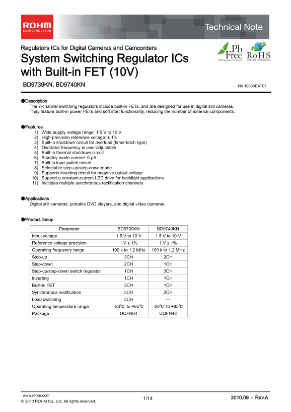
System Switching Regulator ICs with Built-in FET (10V) BD9739KN, BD9740KN No.10036EAT07 ●Description The 7-channel switching regulators include built-in FETs, and are designed for use in digital still cameras. They feature built-in power FETs and soft start functionality, reducing the number of external components.

●Features 1) Wide supply voltage range: 1.5 V to 10 V 2) High-precision reference voltage: ± 1% 3) Built-in shutdown circuit for overload (timer-latch type) 4) Oscillator frequency is user-adjustable 5) Built-in thermal shutdown circuit 6) Standby mode current: 0 μA 7) Built-in load switch circuit 8) Selectable step-up/step-down mode 9) Supports inverting circuit for negative output voltage 10) Support a constant-current LED drive for backlight applications 11) Includes multiple synchronous rectification channels

●Applications Digital still cameras, portable DVD players, and digital video cameras.

●Product lineup

Parameter BD9739KN BD9740KN

Input voltage 1.5 V to 10 V 1.5 V to 10 V Reference voltage precision 1 V ± 1% 1 V ± 1% Operating frequency range 100 k to 1.2 MHz 100 k to 1.2 MHz Step-up 3CH 2CH Step-down 2CH 1CH Step-up/step-down switch regulator 1CH 3CH Inverting 1CH 1CH Built-in FET 3CH 1CH Synchronous rectification 3CH 2CH Load switching 3CH — Operating temperature range -20℃ to +85℃ -20℃ to +85℃ Package UQFN64 UQFN48

www.rohm.com 2010.09 - Rev.A

© 2010 ROHM Co., Ltd. All rights reserved.

Page Summary Contents For rohm BD9740KN Technical Note

Page 1 Regulators ICs for Digital Cameras and Camcorders System Switching Regulator ICs with Built-in FET (10V) BD9739KN, BD9740KN No.10036EAT07 ●Description The 7-channel switching regulators include built-...
Page 2 BD9739KN,BD9740KN Technical Note ●Absolute maximum ratings Ratings Parameter Symbol Unit BD9739KN BD9740KN VBAT,VCC,PVCC -0.3 to +12 -0.3 to +12 V PVCCH,PVCCL -0.3 to +15 -0.3 to +15 V DRAIN*H, DRAIN*...
Page 3 BD9739KN,BD9740KN Technical Note ●Electrical characteristics (Unless otherwise specified, Ta = 25℃, VBAT = 3 V, VCC = 5 V, RT = 11 k, CT = 180 p F, STB1 to STB7 = 3 V) Limits Parameter Symbol Unit Co...
Page 4 BD9739KN,BD9740KN Technical Note (Unless otherwise specified, Ta = 25℃, VBAT = 3 V, VCC = 5 V, RT = 11 kΩ, CT = 180 p F, STB1 to STB7 = 3 V) Limits Parameter Symbol Unit Conditions Min. Typ. Max. [Pow...
Page 5 BD9739KN,BD9740KN Technical Note ●Block diagram and application circuit (BD9739KN) Connect a capacitor to prevent For more information Connect a capacitor to prevent oscillation to the VREF pin. about...
Page 6 BD9739KN,BD9740KN Technical Note ●Block diagram and application circuit (2) BD9740KN Connect a capacitor to prevent For more information Connect a capacitor to prevent oscillation to the VREF pin. abo...
Page 7 BD9739KN,BD9740KN Technical Note ●BD9739KN Pin No. Pin No. Pin name Pin No. Pin name Pin No. Pin name 61 VBAT 60 OUT1B 44,36 NON5,7 29 VCC 4,5,12,13 DRAIN2,3H 28 SS1 54 PVCC 6,7,10,11 DRAIN2,3L 25 SS2...
Page 8 BD9739KN,BD9740KN Technical Note 6. Setting the oscillating frequency The oscillating frequency can be set by connecting the resistance value to the RT pin and connecting the capacitance value to the ...
Page 9 BD9739KN,BD9740KN Technical Note 10. Setting MAX DUTY The DTC voltage is determined by the internal R1 and R2 resistance values. The DTC voltage can be changed by connecting resistance values that are...
Page 10 BD9739KN,BD9740KN Technical Note ●I/O Equivalent circuit diagrams DTC5 to DTC7 INV2 to INV6, INV7 V INV1 (dead time control) (error amp inverted input) (error amp inverted input) VREGA VREGA Vcc VREGA...
Page 11 BD9739KN,BD9740KN Technical Note STBY1 to STBY7 (CH1 to CH7 on/off control) 7CH (power transistor drain output) REGON (CCD REG control input) MODE (CCD sequence control pin) OUT7B STBY1 to STBY7 Vcc R...
Page 12 BD9739KN,BD9740KN Technical Note ●Notes for use 1) Absolute maximum ratings An excess in the absolute maximum ratings, such as supply voltage, temperature range of operating conditions, etc., can brea...
Page 13 BD9739KN,BD9740KN Technical Note 13) Ground wiring patterns The power supply and ground lines must be as short and thick as possible to reduce line impedance. Fluctuating voltage on the power ground l...
Page 14 BD9739KN,BD9740KN Technical Note ●Ordering part number Package 0. ±0 .0 7. ±0 .1 Part No. Part No. Packaging and forming specification KN: UQFN64 E2: Embossed tape and reel UQFN48 UQFN64 8.2±0.1 <T...
Page 15 Notice No copying or reproduction of this document, in part or in whole, is permitted without the consent of ROHM Co.,Ltd. The content specified herein is subject to change for improvement without not...

Manual Details

Brand ROHM
Pages 15
File Size 393.38 KB
Published June 01, 2026
66 views

Enter the captcha to get the download link:

captcha

Frequently Asked Questions

What is the operating temperature range for these regulators?

The operating temperature range is -20℃ to +85℃.

How can I adjust the oscillator frequency?

The oscillator frequency of the ICs is user-adjustable, ranging from 100 k to 1.2 MHz.

What are the main applications for these regulators?

They are designed for use in digital still cameras, portable DVD players, and digital video cameras.

Does it offer built-in protection features?

Yes, they include a built-in shutdown circuit for overload (timer-latch type), thermal shutdown, and an under voltage lockout circuit.