ROHM RPM5300 series User Guide
Summary
This high-sensitivity IR receiver module is engineered for detecting remote control signals across various household electric appliances, including TVs, AC units, and audio equipment. Featuring low power consumption and multiple operating frequencies, it offers reliable signal capture within small SMD designs. This comprehensive manual provides detailed electrical and optical specifications, operational ratings, usage notes, and measurement guidelines necessary for seamless integration into consumer electronics projects.
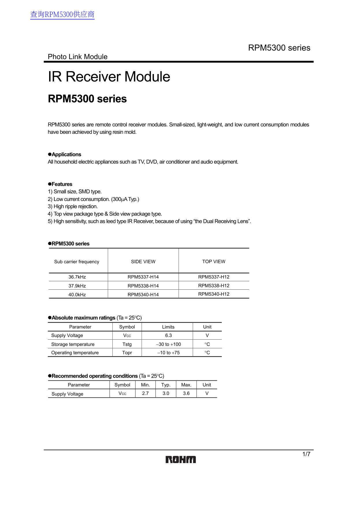
Page 1 Text Content
查询RPM5300供应商
RPM5300 series
Photo Link Module
IR Receiver Module RPM5300 series RPM5300 series are remote control receiver modules. Small-sized, light-weight, and low current consumption modules have been achieved by using resin mold.
Applications All household electric appliances such as TV, DVD, air conditioner and audio equipment.
Features 1) Small size, SMD type. 2) Low current consumption. (300µA Typ.) 3) High ripple rejection. 4) Top view package type & Side view package type. 5) High sensitivity, such as leed type IR Receiver, because of using “the Dual Receiving Lens”.
RPM5300 series
Sub carrier frequency SIDE VIEW TOP VIEW
36.7k Hz RPM5337-H14 RPM5337-H12
37.9k Hz RPM5338-H14 RPM5338-H12 40.0k Hz RPM5340-H14 RPM5340-H12
Absolute maximum ratings (Ta = 25°C) Parameter Symbol Limits Unit
Supply Voltage VCC 6.3
Storage temperature Tstg −30 to +100 °C
Operating temperature Topr −10 to +75 °C
Recommended operating conditions (Ta = 25°C) Parameter Symbol Min. Typ. Max. Unit
Supply Voltage VCC 3.0 3.6 V2.7
Page Summary Contents For ROHM RPM5300 series User Guide
Manual Details
| Brand | ROHM |
|---|---|
| Pages | 8 |
| File Size | 102.38 KB |
| Published | July 12, 2026 |
Enter the captcha to get the download link:

Frequently Asked Questions
What types of household appliances are compatible with this module?
It is suitable for all household electric appliances such as TVs, DVD players, air conditioners, and audio equipment.
What conditions limit the use of this IR receiver module?
The receiver was designed solely for indoor use and cannot cover characteristics when used outdoors.
What voltage range should be supplied to operate the module?
The recommended operating condition (VCC) is a typical range between 3.0 V and 3.6 V, with an absolute limit of 6.3 V.
Is there a specific requirement for the transmitter when using this receiver?
Yes, the transmitter's carrier frequency must be set to the same f0 frequency as the receiver’s operating frequency to prevent errors.