ROHM DTA144GUA User's Guide DTA144GKA Installation Manual
Summary
These specialized digital transistors are designed with built-in resistors, simplifying circuit design and allowing high mounting densities in low-power applications. This manual provides comprehensive technical data, including absolute maximum ratings, full electrical characteristics (like hFE and fT), detailed schematics, and packaging specifications. Optimal for electronics designers developing communication devices, office automation equipment, or general consumer electronics where reliable on/off switching is required.
Page 1 Text Content
DTA144GUA / DTA144GKA
Transistors
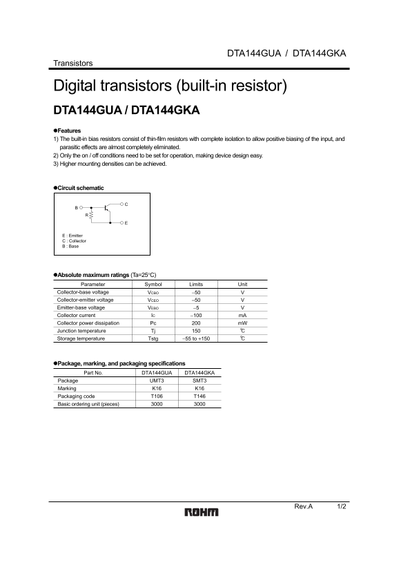
Digital transistors (built-in resistor) DTA144GUA / DTA144GKA Features 1) The built-in bias resistors consist of thin-film resistors with complete isolation to allow positive biasing of the input, and parasitic effects are almost completely eliminated. 2) Only the on / off conditions need to be set for operation, making device design easy. 3) Higher mounting densities can be achieved.
Circuit schematic
E : Emitter C : Collector B : Base
Absolute maximum ratings (Ta=25°C) Parameter Symbol Limits Unit Collector-base voltage VCBO −50 Collector-emitter voltage VCEO −50 Emitter-base voltage VEBO −5
Collector current IC −100 m A
Collector power dissipation Pc m W Junction temperature Tj Storage temperature Tstg −55 to +150
Package, marking, and packaging specifications
Part No. DTA144GUA DTA144GKA
Package UMT3 SMT3 Marking K16 K16 Packaging code T106 T146
Basic ordering unit (pieces)
Rev.A 1/2
Page Summary Contents For ROHM DTA144GUA User's Guide DTA144GKA Installation Manual
Manual Details
| Brand | ROHM |
|---|---|
| Pages | 3 |
| File Size | 61.26 KB |
| Published | May 29, 2026 |
Enter the captcha to get the download link:

Frequently Asked Questions
What is the recommended use environment for these transistors?
The products are designed for use with ordinary electronic equipment or devices, such as audio visual equipment and office automation.
How do I interpret the electrical specifications?
The listed data (including circuit diagrams) are illustrative examples of standard use and operation and should not be treated as definitive specifications. Always consult a representative for precise specs.
Do I need special warnings if using them in critical systems?
If intending to use these products in systems requiring extremely high reliability (like medical or aerospace equipment), you must consult with a sales representative before use.
What are the key operating limits for collectors and emitters?
The absolute maximum ratings limit collector-emitter voltage (VCEO) and collector current ($ ext{I}_ ext{C}$) at $-50 ext{ V}$ and $-100 ext{ mA}$, respectively.