ROHM 2SB1707 User's Manual
Summary
The 2SB1707 is a high-performance NPN transistor designed for reliable use as a low-frequency amplifier and driver component. This technical manual provides comprehensive specifications necessary for design engineers, detailing electrical characteristics such as current gain ($h_{FE}$), collector saturation voltage ($V_{CE(sat)}$), and power dissipation limits. The datasheet covers operational parameters across extended temperature ranges (from -40°C to 125°C) and includes detailed graphs on switching time, making it ideal for integrating into general electronic devices like audio-visual or communication equipment that require stable amplification.
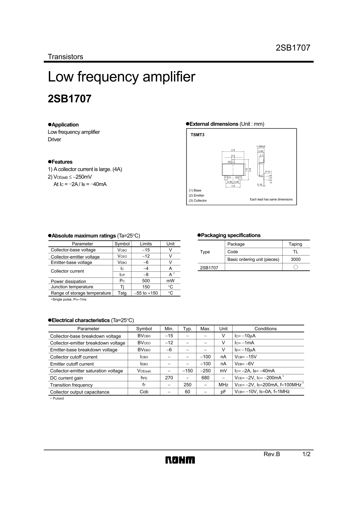
Page 1 Text Content
2SB1707
Transistors
Low frequency amplifier 2SB1707
Application External dimensions (Unit : mm)
Low frequency amplifier
TSMT3
Driver
1.0MAX
Features (3)
1) A collector current is large. (4A)
2) VCE(sat) ≤ −250m V (2)(1) 0.950.95
At IC = −2A / IB = −40m A 0.16
(1) Base (2) Emitter
(3) Collector Each lead has same dimensions
Absolute maximum ratings (Ta=25°C) Packaging specifications
Parameter Symbol Limits Unit Package Taping
1. Collector-base voltage VCBO −15 2.
Type Code TL
Collector-emitter voltage VCEO −12
Basic ordering unit (pieces)
Emitter-base voltage VEBO −6
IC −4 2SB1707
Collector current 0. 3~ 0.
ICP −8 Power dissipation PC m W
Junction temperature Tj °C Range of storage temperature Tstg −55 to +150 °C ∗Single pulse, PW=1ms
Electrical characteristics (Ta=25°C)
Parameter Symbol Min. Typ. Max. Unit Conditions
Collector-base breakdown voltage BVCBO −15 IC= −10µA
Collector-emitter breakdown voltage BVCEO −12 IC= −1m A
Emitter-base breakdown voltage BVEBO −6 IE= −10µA
Collector cutoff current ICBO −100 n A VCB= −15V
Emitter cutoff current IEBO −100 n A VEB= −6V
Collector-emitter saturation voltage VCE(sat) −150 −250 m V IC= −2A, IB= −40m A DC current gain h FE VCE= −2V, IC= −200m A Transition frequency f T MHz VCE= −2V, IE=200m A, f=100MHz
Collector output capacitance Cob p F VCB= −10V, IE=0A, f=1MHz
∗ Pulsed
Rev.B 1/2
Page Summary Contents For ROHM 2SB1707 User's Manual
Manual Details
| Brand | ROHM |
|---|---|
| Pages | 3 |
| File Size | 66.88 KB |
| Published | June 22, 2026 |
Enter the captcha to get the download link:

Frequently Asked Questions
Is this transistor suitable for life-supporting equipment?
No, it is designed for ordinary electronics; users needing extreme reliability must consult sales representatives.
What is the maximum recommended single pulse collector current?
The maximum permissible single pulse collector current (ICp) limit is -8A.
What are the required operating temperatures for storage?
The device has a wide storage temperature range, from -55°C to +150°C.
What is the primary intended application of this model?
It is specifically designated as a Low frequency amplifier.