Rockwell Automation 800HL Potentiometer User's Manual and Instructions
Summary
This comprehensive guide provides detailed instructions for installing and maintaining Allen-Bradley NEMA 7 and 9 Potentiometers. It covers everything from initial assembly—including mounting hardware and electrical clearance warnings—to expert component replacement of the internal potentiometer unit. Essential reading for industrial technicians, engineers, and maintenance personnel needing accurate procedures to service or install these critical control components in rigorous panel environments.
Page 1 Text Content
INSTALLATION INSTRUCTIONS 800HL-EMP POTENTIOMETER FOR NEMA TYPE 7 [3/8" (9.5) TO 2-1/2" (50.8) PANELS] AND TYPE 9 [7/32" (7.2) TO 2-1/2" (50.8) PANELS] Ä
To avoid damage to equipment or injury to personnel, electrical power
WARNING
must be off before and during installation and maintenance.
current-carrying parts and enclosure.
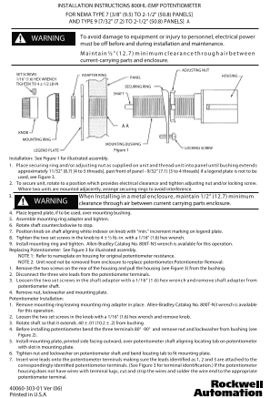
ADJUSTING NUT
SET SCREWS ADAPTER RING HOUSING
1/16" (1.6) HEX WRENCH PANEL
TIGHTEN TO 4 ± 1/2 LB-IN
SECURING RING
SHAFT
KNOB MOUNTING RING
MOUNTING BUSHING
LOCKING SCREW
LEGEND PLATE Figure 1
Installation: See Figure 1 for illustrated assembly. 1. Place securing ring and/or adjusting nut as supplied on unit and thread unit into panel until bushing extends approximately 11/32" (8.7) [4 to 5 threads], past front of panel - 9/32" (7.1) [3 to 4 threads] if a legend plate is not to be used, see Figure 3. 2. To secure unit, rotate to a position which provides electrical clearance and tighten adjusting nut and/or locking screw. Where two units are mounted adjacently, arrange securing rings to avoid interference. 3. When Installing in a metal enclosure, maintain 1/2” (12.7) minimum
WARNING clearance through air between current carrying parts enclosure. 4. Place legend plate, if to be used, over mounting bushing.
5. Assemble mounting ring adapter and tighten. 6. Rotate shaft counterclockwise to stop. 7. Position knob on shaft aligning white indexer on knob with "min." increment marking on legend plate. 8. Tighten the two set screws in the knob to 4 ± ½ lb.-in. with a 1/16" (1.6) hex wrench. 9. Install mounting ring and tighten. Allen-Bradley Catalog No. 800T-N3 wrench is available for this operation. Replacing Potentiometer: See Figure 3 for illustrated assembly. NOTE 1: Refer to nameplate on housing for original potentiometer resistance. NOTE 2: Unit need not be removed from enclosure to replace potentiometer.Potentiometer Removal: 1. Remove the two screws on the rear of the housing and pull the housing (see Figure 3) from the bushing. 2. Disconnect the three wire leads from the potentiometer terminals. 3. Loosen the two set screws in the shaft adapter with a 1/16" (1.6) hex wrench and remove shaft adapter from potentiometer shaft. 4. Remove nut, lockwasher and mounting plate. Potentiometer Installation: 1. Remove mounting ring leaving mounting ring adapter in place. Allen-Bradley Catalog No. 800T-N3 wrench is available for this operation. 2. Loosen the two set screws in the knob with a 1/16" (1.6) hex wrench and remove knob. 3. Rotate shaft so that it extends .40 ± .01 (10.2 ± .2) from bushing. 4. Before installing potentiometer bend the three terminals 80° -90° and remove nut and lockwasher from bushing (see Figure 2). 5. Install mounting plate, printed side facing outward, over potentiometer shaft aligning locating tab on potentiometer with slot in mounting plate. 6. Tighten nut and lockwasher on potentiometer shaft and bend locating tab to fit mounting plate. 7. Insert wire leads onto the potentiometer terminals making sure the leads identified as 1, 2 and 3 are attached to the correspondingly identified potentiometer terminals. (See Figure 3 for terminal identification.) If the potentiometer housing does not have wires with terminal lugs, cut and strip the wires and solder the wire end to the appropriate potentiometer terminal.
40060-303-01 Ver (06) Printed in U.S.A
Page Summary Contents For Rockwell Automation 800HL Potentiometer User's Manual and Instructions
Manual Details
| Brand | Rockwell Automation |
|---|---|
| Pages | 2 |
| File Size | 117.62 KB |
| Published | June 04, 2026 |
Enter the captcha to get the download link:
