# A B C D E F G H I J K L M N O P Q R S T U V W X Y Z

Rockwell Automation ICS Regent RTD Input Equipment User Manual and Instructions

Summary

This RTD Input Equipment system provides reliable, high-safety terminations and temperature conversion for up to 16 Platinum Pt100 RTD inputs in demanding industrial environments. The manual details the comprehensive setup involving the input module, multiplexer, termination panel, and cable infrastructure. Designed primarily for process control engineers and automation systems requiring extreme reliability, it features advanced fault detection, triplicated safety circuits, and seamless remote monitoring up to 50 feet away from the main chassis.
📄 Preview 📖 Table of Contents Contents PAGE OF 26

Page 1 Text Content

ICS Regent® PD-6037

RTD Input Equipment Input Module, Mux, Termination Panel and Cable (T3432-IM, T3432-Mux, T3432-TP and T3432-CA)

Issue 1, March, 06

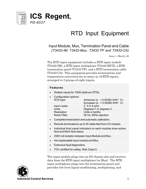
The RTD input equipment includes a RTD input module (T3432-IM), a RTD input multiplexer (T3432-MUX), a RTD termination panel (T3432-TP), and a RTD termination cable (T3432-CA). This equipment provides terminations and temperature conversion for as many as 16 RTD inputs, arranged in 2 groups of eight inputs. Features · Sixteen inputs for 100W platinum RTDs. · Configuration options: RTD type: American (a = 0.00392 W/W/° C) European (a = 0.00385 W/W/° C) Input Leads: 2, 3 or 4-wire Units: Degrees F or degrees C Resolution: Units or tenths Noise Filter: 50 Hz, 60Hz rejection · Complete linearization and automatic calibration. · Remote terminations up to 50 cable feet from I/O chassis. · Individual front panel indicators on each module show active, fault and MUX fault status. · 2500 volt isolation between Input Module and Mux. · Hot-replaceable input module and Mux. · Extensive fault diagnostics. · TÜV certified for safety, Risk Class 5.

The input module plugs into an I/O chassis slot and receives data from the RTD input multiplexer (or Mux). The RTD input multiplexer plugs into the termination panel and provides low level signal conditioning, multiplexing, and

Industrial Control Services 1

Page Summary Contents For Rockwell Automation ICS Regent RTD Input Equipment User Manual and Instructions

Page 1 ICS Regent® PD-6037 RTD Input Equipment Input Module, Mux, Termination Panel and Cable (T3432-IM, T3432-Mux, T3432-TP and T3432-CA) Issue 1, March, 06 The RTD input equipment includes a RTD input modu...
Page 2 RTD Input Equipment (T3432) analog-to-digital conversion. The termination panel can be located as far as 50 cable feet from the I/O chassis. Each module’s triplicated I/O Safetybus interface ensures t...
Page 3 RTD Input Equipment (T3432) Figure 1. Block Diagram of the RTD Input Equipment. The Serial data received from the Mux is optically coupled at the input module to provide electrical isolation. The inpu...
Page 4 RTD Input Equipment (T3432) After receiving the voted data read request, the microcomputer transmits the conditioned temperature data to the Safetybus interface. This interface places the voted temper...
Page 5 RTD Input Equipment (T3432) how to address that module and its points specifically. If a module is removed, or is replaced with a module of a different type, the processor modules will indicate an I/O...
Page 6 RTD Input Equipment (T3432) Figure 3. RTD Input Module. Industrial Control Services
Page 7 RTD Input Equipment (T3432) Termination Panel and Multiplexer Figure 4 shows the physical features of the RTD termination panel and multiplexer. The multiplexer plugs into the termination panel and is...
Page 8 RTD Input Equipment (T3432) Figure 4. RTD Termination Panel and Multiplexer. Application Simplex Configuration A single RTD input module and multiplexer provide a suitable interface to non-critical in...
Page 9 RTD Input Equipment (T3432) Figure 5. Simplex RTD Input Configuration. Fault Tolerant Configurations For safety-critical inputs, redundant input modules and multiplexers are used in a 2oo3 or 1oo2 fau...
Page 10 RTD Input Equipment (T3432) Figure 6. Fault Tolerant RTD Input Configuration, Single Sensor. Figure 7. Fault Tolerant RTD Input Configuration, Redundant Sensors. Industrial Control Services
Page 11 RTD Input Equipment (T3432) RTD Multiplexer Configuration The RTD input multiplexer provides jumpers to configure the RTD types, noise filtering, temperature units, and temperature resolution. All RTD...
Page 12 RTD Input Equipment (T3432) Figure 9. Selecting American or European Type RTDs. Selecting 2, 3 or 4-wire RTD Input Lead Configuration. To select the lead configuration for the RTDs, position the jumpe...
Page 13 RTD Input Equipment (T3432) posts as illustrated in Figure 11 to configure the type of current sources installed on the termination panel. Figure 11. Selecting 1m A or 5m A Current Source. Noise Filte...
Page 14 RTD Input Equipment (T3432) Position the jumper on the posts as illustrated in Figure 13 for the desired temperature units. The temperature data resolution must also be configured for units (data incr...
Page 15 RTD Input Equipment (T3432) Table 1. Temperature Data Ranges. Out-of-Range Detection When the RTD measures temperatures outside of the operating range listed in Table 1, the signal is considered to be...
Page 16 RTD Input Equipment (T3432) 1. For unused input channels, short the +SENSE, -SENSE, and -FORCE terminals together. This will eliminate any floating readings for the unused channels. 2. Minimize the re...
Page 17 RTD Input Equipment (T3432) Figure 14. Mounting Dimensions for the RTD Termination Panel. Termination Panel Cable The termination panel cable connects a RTD input module to a RTD multiplexer installed...
Page 18 RTD Input Equipment (T3432) Figure 15. Termination Cable Connections. Industrial Control Services
Page 19 RTD Input Equipment (T3432) RTD Terminations RTD wiring is connected to the screw terminals located at the bottom of the termination panel as shown in Figure 16. When terminating RTD wiring, follow th...
Page 20 RTD Input Equipment (T3432) Figure 16. Wiring RTDs to Termination Panel. Keying The I/O chassis can be physically keyed to prevent accidental damage caused by inserting a module into a slot wired for ...
Page 21 RTD Input Equipment (T3432) The slot key positions for the RTD input module is listed in Table 2. Figure 17. Installing Slot Keys. Table 2. Slot Key Positions. Module Upper Lower Connector Connector T...
Page 22 RTD Input Equipment (T3432) Configuration Each input module is configured using the WINTERPRET I/O Configuration Editor. In the editor, you will perform the three steps described below to configure th...
Page 23 RTD Input Equipment (T3432) Figure 19. Defining a RTD Input Point. Programming Inputs are referenced in the application program through the tag names defined in the I/O Configuration Editor. The RTD i...
Page 24 RTD Input Equipment (T3432) In this illustration, VALUE_A_NAME, VALUE_B_NAME, and VALUE_C_NAME represent the three RTD inputs to be mid-value selected. ERROR_A_NAME, ERROR_B_NAME and ERROR_C_NAME are ...
Page 25 RTD Input Equipment (T3432) points of failure and extend fault tolerance to include the RTDs. For additional safety considerations, please refer to the Safety Considerations section of the Regent User...
Page 26 RTD Input Equipment (T3432) Common Mode Rejection 100 d B @ 50/60 Hz 60 d B minimum, elsewhere Normal Mode Rejection 70 d B typical Termination Panel Cable Maximum 50 cable feet Length (15 m) Isolatio...

Manual Details

Brand Rockwell Automation
Pages 26
File Size 3.38 MB
Published June 05, 2026
58 views

Enter the captcha to get the download link:

captcha

Frequently Asked Questions

How many RTD inputs can this equipment accommodate?

It supports up to sixteen inputs, arranged in two groups of eight inputs.

What is the maximum distance for termination wiring?

The maximum allowable cable length—from the termination panel to the Mux—is 50 feet.

How is redundancy and fault tolerance achieved?

Fault tolerance can be established by using three input modules and three multiplexers, allowing replacement without signal interruption.

What are the normal operational temperature ranges?

Normal operation is rated from -200° to +800° C. The over-range extends to +883° C.