Philips Semiconductors BT136X series Electrical Data Handbook
Summary
The BT136X series sensitive gate triac is a robust component designed for general-purpose bidirectional switching and phase control in power electronics applications. This manual provides comprehensive technical specifications, including detailed dynamic ratings, thermal resistance values, and absolute maximum limits. It is essential reading for electrical engineers and designers implementing sophisticated AC motor controls or power supply systems requiring high reliability and accurate switching performance.
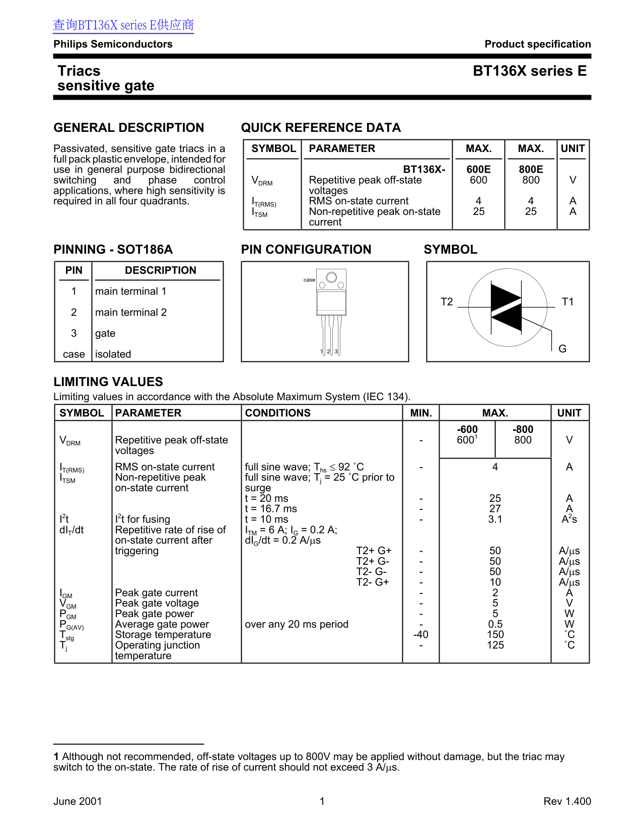
Page 1 Text Content
查询BT136X series E供应商 Philips Semiconductors Product specification
Triacs BT136X series E sensitive gate
GENERAL DESCRIPTION QUICK REFERENCE DATA Passivated, sensitive gate triacs in SYMBOL PARAMETER MAX. MAX. UNIT full pack plastic envelope, intended for use in general purpose bidirectional BT136X- 600E 800E
switching and phase control VDRM Repetitive peak off-state
applications, where high sensitivity is voltages
required in all four quadrants. IT(RMS) RMS on-state current
ITSM Non-repetitive peak on-state
current
PINNING - SOT186A PIN CONFIGURATION SYMBOL PIN DESCRIPTION
main terminal 1
main terminal 2 gate
case isolated
LIMITING VALUES Limiting values in accordance with the Absolute Maximum System (IEC 134). SYMBOL PARAMETER CONDITIONS MIN. MAX. UNIT
VDRM Repetitive peak off-state
voltages
IT(RMS) RMS on-state current full sine wave; Ths ≤ 92 ˚C ITSM Non-repetitive peak full sine wave; Tj = 25 ˚C prior to
on-state current surge
t = 20 ms t = 16.7 ms
I2t I2t for fusing t = 10 ms 3.1 A2s d IT/dt Repetitive rate of rise of ITM = 6 A; IG = 0.2 A;
on-state current after d IG/dt = 0.2 A/µs triggering T2+ G+ A/µs
IGM Peak gate current VGM Peak gate voltage PGM Peak gate power PG(AV) Average gate power over any 20 ms period 0.5 Tstg Storage temperature -40 ˚C Tj Operating junction ˚C
temperature
1 Although not recommended, off-state voltages up to 800V may be applied without damage, but the triac may switch to the on-state. The rate of rise of current should not exceed 3 A/µs.
June 2001 Rev 1.400
Page Summary Contents For Philips Semiconductors BT136X series Electrical Data Handbook
Manual Details
| Brand | Philips |
|---|---|
| Pages | 6 |
| File Size | 37.92 KB |
| Published | July 15, 2026 |
Enter the captcha to get the download link:

Frequently Asked Questions
What are these components primarily designed for?
They are intended for general purpose bidirectional switching and phase control in applications like voltage regulation.
What should I be aware of regarding maximum off-state voltages?
While up to 800V may be applied without damage, the rate of rise of current must not exceed 3 A/μs.
Are these triacs suitable for life support applications?
No, they are explicitly not designed for use in life support appliances or systems.
What is the typical thermal resistance from junction to heatsink (th j-hs)?
The typical thermal resistance when using a heatsink compound is 5.5 K/W.