Philips Semiconductor NE5565 Electronic Ballast Controller Circuit (1) User's Manual
Summary
Philips semiconductor discrete component datasheet. Documents maximum ratings (voltage, current, power dissipation), thermal characteristics, DC/AC electrical specifications, typical performance curves, S-parameters for RF applications, package mechanical drawings, marking codes, and ESD handling precautions in antistatic packaging.
Page 1 Text Content
Philips Semiconductors Product specification 现货库存、技术资料、百科信息、热点资讯,精彩尽在鼎好!
NE5565Electronic ballast controller circuit
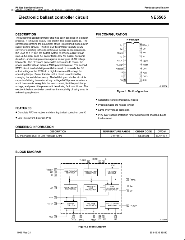
DESCRIPTION PIN CONFIGURATION The Electronic Ballast controller chip has been designed in a bipolar
N Package
process. It is housed in a 20-lead dual-in-line plastic package. The control chip contains the equivalent of two (2) switched mode power
DCOUTCT
supply control circuits. The first SMPS controller is a DC-to-DC
CP DC
converter operating in the discontinuous current conduction mode.
It is used as a PFC in the ballast system to provide a DC voltage DMAX OV
step-up function, good AC power factor, low AC current harmonic PF
distortion, and circuit protection against some types of AC voltage
RXCX VREF
transients. The PFC uses pulse width modulation to control the
VLAMP IPRIM
power transfer with an external MOS power transistor. The second SMPS circuit is a half-bridge oscillator circuit. It converts the DC CRECT OUTH output voltage of the PFC into a high frequency AC voltage for
LI2 VCC
operating lamps. Power transfer in this circuit is controlled by
LI OUTP
changing the switch frequency. The half-bridge controller circuit is
capable of driving two external high voltage MOS power transistors CSI GND
and it has circuits to regulate the lamp current, limit the peak lamp
voltage, and protect the power switches during fault conditions. This SL00524
electronic ballast controller circuit has the capability of being used in
Figure 1. Pin Configuration
a dimming application.
Selectable variable frequency modes
Programmable pre-hit and ignition
FEATURES:
Lamp over-voltage protection
Complete PFC correction and dimming ballast control on one IC
PFC over-voltage protection for preventing over-shooting due to
Low line current distortion PFC load removal
ORDERING INFORMATION
DESCRIPTION TEMPERATURE RANGE ORDER CODE DWG #
20-Pin Plastic Dual-In-Line Package (DIP) 0 to +85°C NE5565N SOT146-1
BLOCK DIAGRAM
RTRXCXVLAMP
CRECT LI2 LI
DCOUT
OUTH IPRIM VREF PF OV DC SL00525
Figure 2. Block Diagram
11996 May 21 853-1835 16843
Page Summary Contents For Philips Semiconductor NE5565 Electronic Ballast Controller Circuit (1) User's Manual
Manual Details
| Brand | Philips |
|---|---|
| Pages | 6 |
| File Size | 83.40 KB |
| Published | June 18, 2026 |
Enter the captcha to get the download link:

Frequently Asked Questions
Does this chip perform Power Factor Correction (PFC)?
Yes, the chip contains a DC-to-DC converter operating as a PFC in the ballast system.
What are the main functions of the half-bridge circuit?
It converts the PFC output voltage into high frequency AC voltage for lighting lamps and controls power transfer by varying the switch frequency.
What is the ambient temperature range for operation?
The electronic ballasts controller chip operates in a temperature range of 0 to +85°C.