Page 1
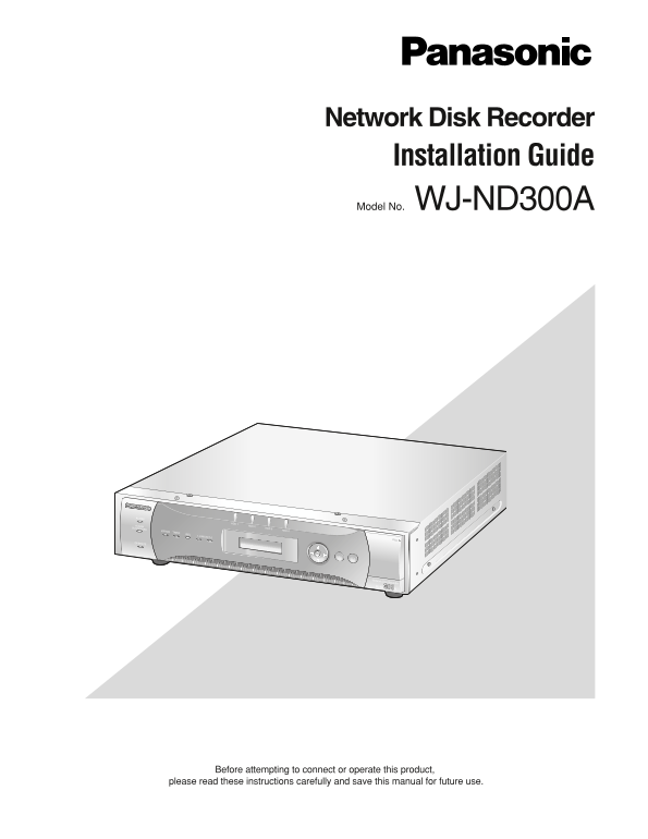
Network Disk Recorder Installation Guide Model No. WJ-ND300A ALARM HDD 1 ALARMSUSPENDED HDD 2 HDD 3 HDD 4 ERROR TIMER REC 1-LINK/ACT-2 OPERATE ESC SET Network Disc Recorder WJ-ND300A Before attempting...
Page 2
We declare under our sole responsibility that the product to which this Wij verklaren als enige aansprakelijke, dat het product waarop deze declaration relates is in conformity with the standards or o...
Page 3
For Canada This Class A digital apparatus complies with Canadian ICES-003. For U.S.A NOTE: This equipment has been tested and found to com- ply with the limits for a Class A digital device, pursuant t...
Page 4
Important Safety Instructions 1) Read these instructions. 2) Keep these instructions. 3) Heed all warnings. 4) Follow all instructions. 5) Do not use this apparatus near water. 6) Clean only with dry ...
Page 5
CONTENTS Limitation of Liability ................................................................................................................................... Disclaimer of Warranty ...............
Page 6
Precautions Refer all work related to the installation of this prod- Avoid rapid changes of the temperature/humidity to uct to qualified service personnel or system prevent condensation. (Acceptable c...
Page 7
Indication label any other use. Additional information including that Refer to the indication label placed on the surface of relating to promotional, internal and commercial uses the unit as to the in...
Page 8
Trademarks and Registered Trademarks Adobe, Adobe logos, and Acrobat are registered trademarks of Adobe Systems Incorporated in the U.S. and/or other countries. Microsoft, Windows and Windows XP are r...
Page 9
Preface The Network Disk Recorders WJ-ND300A is designed for use within a surveillance system. The network disk recorder is a recording device using a hard disk drive to record pictures of network cam...
Page 10
Major Operating Controls and Their Functions Front View HDD1 HDD2 HDD3 HDD4 ALARM ALARM SUSPEND ERROR TIMER REC 1-LINK/ACT-2 ESC SET OPERATE Network Disk Recorder Network Disk Recorder WJ-ND AWJ-ND Op...
Page 11
!2 Escape Button (ESC) Use this button to display the previously displayed item on the LCD. !3 Set Button (SET) Use this button to determine the edited settings item on the LCD. !4 Maintenance Port (F...
Page 12
Rack Mounting Important: When installing the unit in the rack without turning the power of the unit off, activate the HDD safety mode. (Refer to page 34 for further information.) Important Do not inst...
Page 13
Connections The following are descriptions of how to connect the unit with PCs, cameras and an optional extension unit. Required devices and cables vary depending on how to connect them. Before starti...
Page 14
Connection between cameras and PCs When connecting the unit and PCs through a hub, use a LAN cable to connect between the unit and a hub. Cameras should also be connected through a hub using LAN cable...
Page 15
<Connecting multiple units> Network Cameras POWER SIGNAL GND ON ALARM AC IN 10/100BASE-T EXT STORAGE SERIAL ALARM/CONTROL PC CAMERA First Unit Network Cameras LAN Cable (Not provided: 10BASE-T/1...
Page 16
Connecting with Extension Unit Up to 6 extension units can be connected with a single network disk recorder. Use the dedicated cable to connect between the external storage (EXT STORAGE) connector on ...
Page 17
When connecting two extension units or more, connect them as follows. Up to 6 extension units can be connected to a single unit. When connecting the units newly, observe the following important notice...
Page 18
How to Use the Terminals of the ALARM/CONTROL Connector These terminals are used for emergency recording, auto time adjustment, taking measures against power outages, and when installing a buzzer, a l...
Page 19
Connection for emergency recording When the external switch is turned ON, emergency recording will be started. Recording time and recording rate for emergency recording differ according to the setting...
Page 20
• When "Auto Adjust Time" of "Time & Date" of "System" on the SETUP MENU is set to "SLAVE" "Time Adjust Input" becomes available. When a signal ou...
Page 21
Connection with the Uninterruptible Power System (UPS) This is an example of connection with the uninterruptible power system (UPS) to be installed to protect from a power outage. When a signal is sup...
Page 22
How to Use the Terminals of the ALARM Connector These terminals are used to connect the alarm devices, such as sensors, door switches, etc. The pin configurations of these terminals are as shown below...
Page 23
Alarm connection When a signal is supplied to the alarm input terminals recording and displaying of camera images will be performed according to the settings. When an alarm device such as a buzzer, a ...
Page 24
How to Replace Hard Disk Drives Replacement of hard disk drives is available regardless of 2. Remove the connector from the front panel. whether the power of the unit is on or off. The procedure of re...
Page 25
Remove the screws (4 for each drive unit) and pull the Important: drive units out. The identification numbers of the built-in hard disk dri- Avoid missing the screws for reattaching. ves are assigned ...
Page 26
When replacing the hard disk drive with the After completing the HDD replacement, attach the unit power on cable to the front panel. The OPERATE indicator will light and the following menu will be dis...
Page 27
Turn On/Off the Power of the Unit Operating the Unit for the First Turn on the Power of the Unit Time 1. Insert the power plug to an outlet. Important: 120 V AC 60 Hz, for NTSC model When connecting a...
Page 28
Turn off the Power of the Unit To shutdown the unit, do the following. 1. When the manual recording is being performed, stop the recording. Click the button in the [REC] box displayed when the [HDD] t...
Page 29
Operation Using the Buttons on the Front Panel The following are the available functions using the buttons on the front panel and the LCD. The display on the LCD will shift as follows by pressing the ...
Page 30
Check the Network Settings It is possible to check the following network settings. DHCP IP address Subnet mask Gateway*1 HTTP port*1 To check each setting, shift the display as follows. Note: To chang...
Page 31
Set the Network Settings It is possible to set the network settings. The available settings items are the same as described in the "Check the Network Settings" section on the previous page. ...
Page 32
Key Lock Settings It is possible to lock the buttons on the front panel to make them unusable. When the [SET] button is pressed while displaying the key lock display, the message of "Keylock Enab...
Page 33
Shift the display on the LCD using the arrows button (C and D). [SET] [ESC] Arrows buttons D Arrows buttons D Arrows buttons D Arrows buttons D Arrows buttons D Important: When the HDD safety mode is ...
Page 34
Set the HDD Safety Mode When installing/uninstalling the unit in the rack without turning the power of the unit off, do the following. (Steps 1, 3 and 4.) 1. Turn off the power of the HDDs. Press the ...
Page 35
Check the Unit Number of the Extension Unit The unit number of the connected extension unit can be checked with the HDD access indicators on the extension unit. [SET] [SET] D Arrows buttons C [SET] D ...
Page 36
Reboot the Unit Manually It is possible to reboot the unit manually as follow. Press the [SET] button while displaying the [REBOOT] display. The message "ACCEPT" will be displayed. When the ...
Page 37
Troubleshooting Check the following before requesting repair Contact a dealer if a problem cannot be solved even after checking and trying the solution or if a problem is not described below, or when ...
Page 38
Problem Check item/Remedy The system error occurred. Refer to the dealer. The system error status will be displayed with the HDD indi- cators as follows. : Red, 9 : Orange 9 8 8 8 : Hardware malfuncti...
Page 39
Specification General Power source NTSC model: 120 V AC, 60 Hz PAL model: 220 V - 240 V AC, 50 Hz Power consumption 85 W Ambient operating °C to 45 °C {41 °F - 113 °F} temperature Ambient operating 5 ...
Page 40
Information on Disposal for Users of Waste Electrical & Electronic Equipment (private households) This symbol on the products and/or accompanying documents means that used electrical and electroni...