Page 1
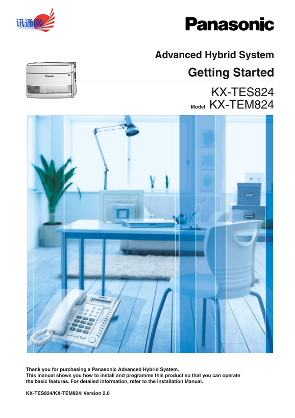
Advanced Hybrid System Getting Started KX-TES824 Model KX-TEM824 Thank you for purchasing a Panasonic Advanced Hybrid System. This manual shows you how to install and programme this product so that yo...
Page 2
System Components System Components Table Model Description Main Unit KX-TES824 Advanced Hybrid System: 3 to 8 Outside (CO) Lines, 8 to 24 Extensions KX-TEM824 Advanced Hybrid System: 6 to 8 Outside (...
Page 3
Expandability of Outside (CO) Lines and Extensions KX-TE82483 KX-TE82480 KX-TE82474 Expanded Outside (CO) Line: 3 Outside (CO) Line: 2 Outside (CO) Line: 0 System Extension: 8 Extension: 8 Extension: ...
Page 4
Important Safety Instructions When using your telephone equipment, basic safety precautions should always be followed to reduce the risk of fire, electric shock and injury to persons, including the fo...
Page 5
16. Keep the unit away from heating appliances and devices that generate electrical noise such as fluorescent lamps, motors and televisions. These noise sources can interfere with the performance of t...
Page 6
For users in New Zealand only This equipment shall not be set to make automatic calls to the Telecom '111' Emergency Service. The grant of a Telepermit for any item of terminal equipment indicates onl...
Page 7
WARNING THIS UNIT MAY ONLY BE INSTALLED AND SERVICED BY QUALIFIED SERVICE PERSONNEL. IF DAMAGE TO THE UNIT EXPOSES ANY INTERNAL PARTS, DISCONNECT THE POWER SUPPLY CORD IMMEDIATELY AND RETURN THE UNIT ...
Page 8
Precautions for Users in the United Kingdom FOR YOUR SAFETY, PLEASE READ THE FOLLOWING TEXT CAREFULLY. This appliance is supplied with a moulded three-pin mains plug for your safety and convenience. A...
Page 9
How to replace the fuse: Open the fuse compartment with a screwdriver and replace the fuse and fuse cover. The equipment must be connected to direct extension lines, and a payphone should not be conne...
Page 10
Table of Contents Before Installation 1.1 Unpacking........................................................................................................................11 1.2 System Connection Diag...
Page 11
Before Installation 1.1 Unpacking Check the package contents. Main Unit × 1 CD-ROM (including manuals, etc.) × 1 *AC Cord × 1 Screw × 3 Washer × 3 Mini Plug (for pager and music Strap × 1 Rivet × 1 so...
Page 12
1.2 System Connection Diagram Outside (CO) Line Remote PC Doorphone Door Opener/Doorbell/ Batteries Door Chime External audio source (radio, CD player, etc.) PCPrinter Paging system (loudspeaker, ampl...
Page 13
Installation 2.1 Opening Covers 1. Loosen the top cover screw. 2. Remove the top front cover. Top front cover Screw Note The screw cannot be removed from the cover. Getting Started
Page 14
2.2 Connecting Outside (CO) Lines 1. Insert the modular plugs of the telephone line cords (2-conductor wiring) into the outside (CO) line jacks. 2. Connect the line cords to the terminal board or the ...
Page 15
2.4 Securing Cords 1. Insert the rivet into the hole in the strap. 2. Insert the rivet and strap into the hole on the PBX. Rivet 3. Wrap the strap around all of the cords. 2.5 Closing Covers 1. Replac...
Page 16
CAUTION Tighten the above screw firmly to prevent the main unit from falling when the PBX is carried. 2. Tie together all of the connected cords and secure them to the wall so that they cannot be pull...
Page 17
2.6 Wall Mounting The PBX is designed for wall mounting only. The wall where the PBX is to be mounted must be able to support the weight of the PBX. When wall mounting the main unit, use either the in...
Page 18
2.6.2 Mounting on a Concrete or Mortar Wall The included screws may be used when mounting the main unit on a concrete or mortar wall. User- supplied anchor plugs are also necessary. 1. Place the templ...
Page 19
Be careful not to drop the cabinet. 2.7 Connecting Frame Earth IMPORTANT Connect the frame of the PBX to earth. 1. Loosen the screw. Earthing wire 2. Insert an earthing wire (user-supplied)*. 3. Tight...
Page 20
Starting the Advanced Hybrid System 3.1 Starting the Advanced Hybrid System This section explains the required procedure for starting the PBX for the first time. 1. Make sure that all outside (CO) lin...
Page 21
To clear outgoing messages (OGMs) for DISA/UCD: e. Enter 599. f. Press the NEXT (SP-PHONE) button. g. Press the STORE (AUTO DIAL/STORE) button. h. Press the END (HOLD) button. 7. Press the PROGRAM but...
Page 22
PC Programming 4.1 PC Programming PBX features and settings can be customised using a PC and the KX-TE Maintenance Console software. Customisation and maintenance can be done easily and efficiently us...
Page 23
PT Programming 5.1 Programming Instructions The PBX can be programmed by entering 3-digit programming numbers with a proprietary telephone (PT). In this manual, how to programme some features through ...
Page 24
Fixed Button (KX-T7730/KX-T7735) Function SELECT FLASH CLEAR Entering System Programming Mode To enter system programming mode, the system password is required. System Password for Programming No. Adm...
Page 25
The PT's dialling buttons can be used to enter characters when storing a name or message. The following tables depict the available characters: Table 1 (Alphabet mode)/Table 2 (Numeral mode) Getting S...
Page 26
Table 3 (Cyrillic alphabet mode for RU [Russia]/UA [Ukraine] model) * This character is only available for the KX-T7735RU. [Example of Entering Characters] To enter "Ann": (5 times) (5 times...
Page 27
5.2.1 Basic Features Date & Time [000] year day NEXT SELECT➞ (00…99) (Jan.…Dec.) (1…31) hour minute STORE ENDSELECT SELECT (Sun…Sat) (1…12) (00…59) (AM/PM) Notes The clock starts immediately after...
Page 28
2. To avoid unauthorised access and possible fraudulent dialling, maintain the secrecy of the password. 3. We strongly recommend that you change the default password value to something else for reason...
Page 29
System Speed Dialling Name [011] NEXT PREVor To continue NEXT speed dialling no. name* STORE END (00…99) Max. 16 characters To continue SELECT Note * A name can be entered using a PT's dialling button...
Page 30
Note This programme is not available for the AL (Australia) model. Extension Name [604] NEXT PREVor To continue extension jack no. extension name* NEXT STORE END (01…24) Max. 10 characters To continue...
Page 31
5.2.2 Toll Restriction (TRS) Features Toll Restriction (TRS) can prohibit certain extension users from making unauthorised outside (CO) line calls. Every extension is assigned to one of 5 classes of s...
Page 32
TRS—COS 2-5 Denied Code [302-305] NEXT PREVor To continue NEXT code no. phone no. STORE END (01…20) Max. 11 digits (0…9, , #, x) To continue 02: for Class 2 03: for Class 3 04: for Class 4 SELECT 05: ...
Page 33
Getting Started
Page 34
Getting Started
Page 35
Install a screw here. Install a screw here. 169 mm 1.2.3.M opy or print this tem plate and place it on the w all. Install the screw s as m arked. If you m ount the m ain unit on a concrete or m ortar ...
Page 36
<Product Documentation for the KX-TES824/KX-TEM824> Electronic documentation for the KX-TES824/KX-TEM824 can be found on the included CD-ROM. To view this documentation, simply insert the CD-ROM...