Panasonic KT4 Series Temperature Controller User's Manual
Summary
The KT4 Temperature Controller offers precise industrial temperature monitoring and control using multiple selectable inputs (Thermocouple, RTD, DC Voltage, DC Current) and versatile outputs. This comprehensive manual serves as an essential guide for operators and technicians, detailing full model number decoding, wiring instructions, and critical safety precautions. It covers setup details, display interpretation (PV/SV), troubleshooting disconnected signals, and ensures proper installation practices to maintain operational integrity in industrial control systems.
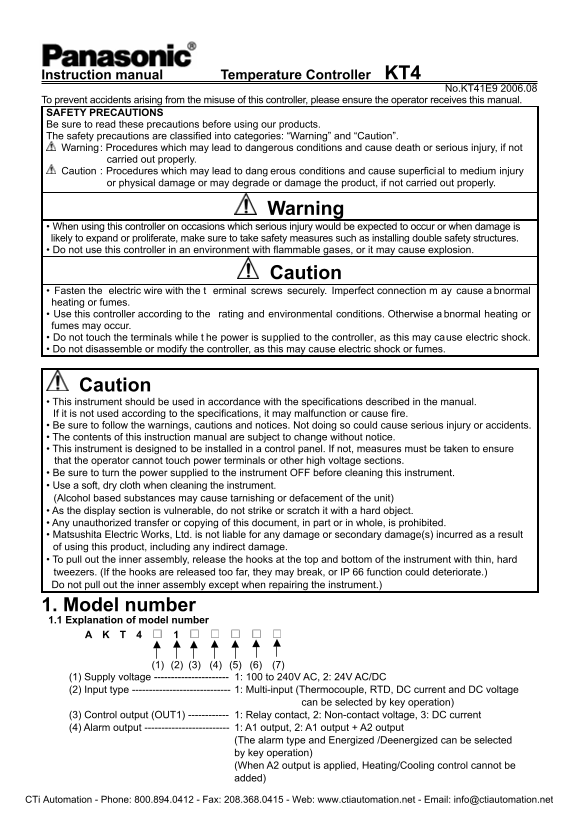
Page 1 Text Content
Instruction manual Temperature Controller KT4
No.KT41E9 2006.08
To prevent accidents arising from the misuse of this controller, please ensure the operator receives this manual. SAFETY PRECAUTIONS Be sure to read these precautions before using our products. The safety precautions are classified into categories: “Warning” and “Caution”. Warning : Procedures which may lead to dangerous conditions and cause death or serious injury, if not carried out properly. Caution : Procedures which may lead to dang erous conditions and cause superficial to medium injury or physical damage or may degrade or damage the product, if not carried out properly.
Warning
• When using this controller on occasions which serious injury would be expected to occur or when damage is likely to expand or proliferate, make sure to take safety measures such as installing double safety structures. • Do not use this controller in an environment with flammable gases, or it may cause explosion.
Caution
• Fasten the electric wire with the t erminal screws securely. Imperfect connection m ay cause a bnormal heating or fumes. • Use this controller according to the rating and environmental conditions. Otherwise a bnormal heating or fumes may occur. • Do not touch the terminals while t he power is supplied to the controller, as this may cause electric shock. • Do not disassemble or modify the controller, as this may cause electric shock or fumes.
Caution • This instrument should be used in accordance with the specifications described in the manual. If it is not used according to the specifications, it may malfunction or cause fire. • Be sure to follow the warnings, cautions and notices. Not doing so could cause serious injury or accidents. • The contents of this instruction manual are subject to change without notice. • This instrument is designed to be installed in a control panel. If not, measures must be taken to ensure that the operator cannot touch power terminals or other high voltage sections. • Be sure to turn the power supplied to the instrument OFF before cleaning this instrument. • Use a soft, dry cloth when cleaning the instrument. (Alcohol based substances may cause tarnishing or defacement of the unit) • As the display section is vulnerable, do not strike or scratch it with a hard object. • Any unauthorized transfer or copying of this document, in part or in whole, is prohibited. • Matsushita Electric Works, Ltd. is not liable for any damage or secondary damage(s) incurred as a result of using this product, including any indirect damage. • To pull out the inner assembly, release the hooks at the top and bottom of the instrument with thin, hard tweezers. (If the hooks are released too far, they may break, or IP 66 function could deteriorate.) Do not pull out the inner assembly except when repairing the instrument.)
1. Model number 1.1 Explanation of model number A K T 4 1
(1) (2) (3) (4) (5) (6) (7) (1) Supply voltage ---------------------- 1: 100 to 240V AC, 2: 24V AC/DC (2) Input type ----------------------------- 1: Multi-input (Thermocouple, RTD, DC current and DC voltage can be selected by key operation) (3) Control output (OUT1) ------------ 1: Relay contact, 2: Non-contact voltage, 3: DC current (4) Alarm output ------------------------- 1: A1 output, 2: A1 output + A2 output
(The alarm type and Energized /Deenergized can be selected by key operation) (When A2 output is applied, Heating/Cooling control cannot be added)
CTi Automation - Phone: 800.894.0412 - Fax: 208.368.0415 - Web: www.ctiautomation.net - Email: [email protected]
Page Summary Contents For Panasonic KT4 Series Temperature Controller User's Manual
Manual Details
| Brand | Panasonic |
|---|---|
| Pages | 20 |
| File Size | 614.30 KB |
| Published | June 17, 2026 |
Enter the captcha to get the download link:

Frequently Asked Questions
What supply voltages does the KT4 support?
It supports 100 to 240V AC or 24V AC/DC supply voltages.
How should I clean the temperature controller?
Turn power off first, then use a soft, dry cloth to clean it.
Why is the PV display flashing []?
Check thermocouple polarity or RTD codes are wired correctly.
Can I use this controller in flammable gas environments?
No, using it in such environments may cause an explosion.