OMRON Smart Sensor (2D Shape Measurement Sensor ZG2 Series) ZG2-WDC Smart Sensor Controller for ZG2-WDS Instruction Sheet
Summary
Optimize your industrial process with this advanced Sensor Controller, designed for high-precision measurement and robust data management. This comprehensive manual provides critical instructions on optimal installation, detailed wiring schematics for diverse analog and digital I/O channels, and necessary operational precautions. It serves as an essential guide for automation engineers and technicians implementing complex machine vision or monitoring systems that require accurate judgment results and reliable integration with host devices.
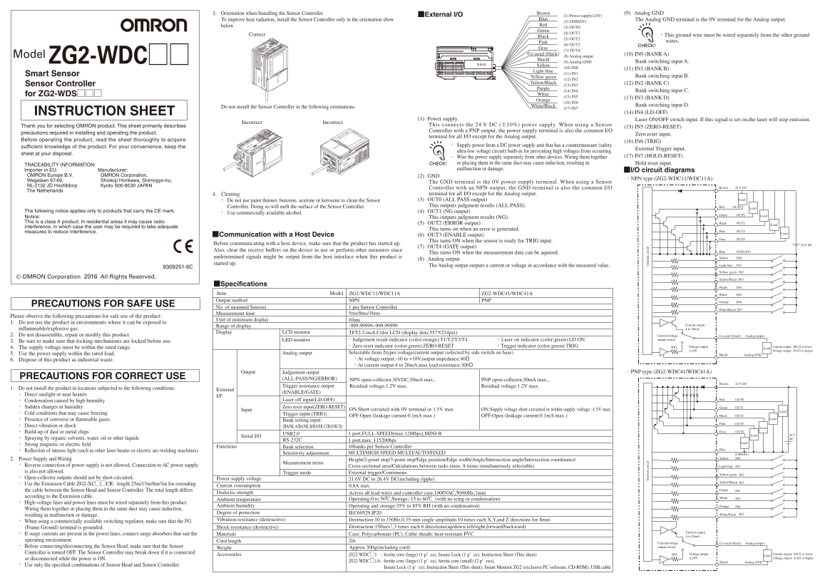
Page 1 Text Content
3. Orientation when Installing the Sensor Controller Brown (9) Analog GND
■External I/O (1) Power supply(24V)
To improve heat radiation, install the Sensor Controller only in the orientation show Blue The Analog GND terminal is the 0V terminal for the Analog output.
(2) GND(0V)
below. Red
(3) OUT0
Green
(4) OUT1
Correct ・This ground wire must be wired separately from the other ground
Black
(5) OUT2
Pink wires.
(6) OUT3
(7) OUT4
Co-axial (black) (10) IN0 (BANK A)
Model ZG2-WDC□□ (8) Analog output Shield
(9) Analog GND Bank switching input A.
Yellow
(10) IN0 (11) IN1 (BANK B)
Light blue
Smart Sensor (11) IN1
Yellow green Bank switching input B.
(12) IN2
Yellow/Black (12) IN2 (BANK C)
Sensor Controller (13) IN3
Purple
(14) IN4 Bank switching input C.
for ZG2-WDS□□□ White (15) IN5 (13) IN3 (BANK D) Orange
(16) IN6
White/Black Bank switching input D.
Do not install the Sensor Controller in the following orientations. (17) IN7
INSTRUCTION SHEET (14) IN4 (LD-OFF)
(1) Power supply Laser ON/OFF switch input. If this signal is set on,the laser will stop emission.
Incorrect Incorrect
Thank you for selecting OMRON product. This sheet primarily describes This connects the 24 V DC (±10%) power supply. When using a Sensor
(15) IN5 (ZERO-RESET)
Controller with a PNP output, the power supply terminal is also the common I/O
precautions required in installing and operating the product. Zero reset input.
terminal for all I/O except for the Analog output.
Before operating the product, read the sheet thoroughly to acquire
(16) IN6 (TRIG)
・ Supply power from a DC power supply unit that has a countermeasure (safety
sufficient knowledge of the product. For your convenience, keep the
External Trigger input.
ultra-low voltage circuit) built-in for preventing high voltages from occurring.
sheet at your disposal.
・ Wire the power supply separately from other devices. Wiring them together (17) IN7 (HOLD-RESET)
or placing them in the same duct may cause induction, resulting in Hold reset input.
TRACEABILITY INFORMATION:
Importer in EU: Manufacturer: malfunction or damage.
■I/O circuit diagrams
OMRON Europe B.V. OMRON Corporation, (2) GND
・NPN type (ZG2-WDC11/WDC11A)
Wegalaan 67-69, Shiokoji Horikawa, Shimogyo-ku,
The GND terminal is the 0V power supply terminal. When using a Sensor
NL-2132 JD Hoofddorp Kyoto. 600-8530 JAPAN
Controller with an NPN output, the GND terminal is also the common I/O Brown 24 V DC
The Netherlands
4. Cleaning terminal for all I/O except for the Analog output.
・ Do not use paint thinner, benzene, acetone or kerosene to clean the Sensor (3) OUT0 (ALL PASS output) Load
Controller. Doing so will melt the surface of the Sensor Controller. This outputs judgment results (ALL PASS). Red OUT0
The following notice applies only to products that carry the CE mark: (4) OUT1 (NG output)
・ Use commercially available alcohol.
Green OUT1 Load
Notice: This outputs judgment results (NG). This is a class A product. In residential areas it may cause radio Black OUT2
(5) OUT2 (ERROR output) Load
interference, in which case the user may be required to take adequate
This turns on when an error is generated.
measures to reduce interference. Pink OUT3
■Communication with a Host Device (6) OUT3 (ENABLE output)
Gray OUT4
This turns ON when the sensor is ready for TRIG input.
Before communicating with a host device, make sure that the product has started up. 24 V DC
(7) OUT4 (GATE output)
Also, clear the receive buffers on the device in use or perform other measures since Blue GND (0V)
This turns ON when the measurement data can be aquired.
undetermined signals might be output from the host interface when this product is Yellow IN0
(8) Analog output
started up.
The Analog output outputs a current or voltage in accordance with the measured value. Light blue IN1
Yellow green IN2
© OMRON Corporation 2016 All Rights Reserved.
Yellow/Black IN3
■Specifications
Purple IN4
Item Model ZG2-WDC11/WDC11A ZG2-WDC41/WDC41A White IN5 Output method NPN PNP IN6Orange
PRECAUTIONS FOR SAFE USE
No. of mounted Sensors 1 per Sensor Controller
IN7White/Black
Measurement time 5ms/8ms/16ms
Please observe the following precautions for safe use of the product:
Unit of minimum display 10nm
1. Do not use the product in environments where it can be exposed to
-999.99999~999.99999 Current output
Range of display
in ammable/explosive gas. 4 to 20m A
Display LCD monitor TFT2.2-inch Color LCD (display dots:557×234pix)
2. Do not disassemble, repair or modify this product. Current/voltage Co-axial (black) Analog output
LED monitor ・Judgement result indicator (color:orange):T1/T2/T3/T4 ・Laser on indicator (color:green):LD ON output switch
3. Be sure to make sure that locking mechanisms are locked before use.
・Zero reset indicator (color:green):ZERO-RESET ・Trigger indicator (color:green):TRIG 40Ω Voltage output Current output: 300 Ω or lower
4. The supply voltage must be within the rated range. Load
±10V Voltage output: 10 kΩ or higher
5. Use the power supply within the rated load. Analog output Selectable from 2types voltage/current output (selected by side switch on base)
Shield Analog GND
6. Dispose of this product as industrial waste. ・At voltage output:-10 to +10V,output impedance:40Ω ・At current output:4 to 20m A,max.load resistance:300Ω
Output Judgement output ・PNP type (ZG2-WDC41/WDC41A)
PRECAUTIONS FOR CORRECT USE (ALL-PASS/NG/ERROR)
NPN open-collector,30VDC,50m A max., PNP open-collector,50m A max.,
Brown 24 V DC
Trigger assistance output Residual voltage:1.2V max. Residual voltage:1.2V max.
1. Do not install the product in locations subjected to the following conditions:
External
(ENABLE/GATE)
・ Direct sunlight or near heaters
Laser off input(LD-OFF) Red OUT0
・ Condensation caused by high humidity
・ Sudden changes in humidity Zero reset input(ZERO-RESET) Green OUT1
Input ON:Short-circuited with 0V terminal or 1.5V max. ON:Supply voltage short-circuited or within supply voltage -1.5V max.
・ Cold conditions that may cause freezing Trigger input (TRIG)
OFF:Open (leakage current:0.1m A max.) OFF:Open (leakage current:0.1m A max.) Black OUT2
・ Presence of corrosive or ammable gases Load
Bank setting input
Pink OUT3
・ Direct vibration or shock (BANK A/BANK B/BANK C/BANK D)
・ Build-up of dust or metal chips Gray OUT4
USB2.0 1 port,FULL-SPEED[max.12Mbps],MINI-B Load 24 V
Serial I/O
・ Spraying by organic solvents, water, oil or other liquids DC
RS-232C 1 port,max. 115200bps
・ Strong magnetic or electric eld
Functions Bank selection 16banks per Sensor Controller
・ Re ection of intense light (such as other laser beams or electric arc-welding machines)
Sensitivity adjustment MULTI/HIGH SPEED MULTI/AUTO/FIXED GND(0V)
2. Power Supply and Wiring Yellow IN0
Height/2-point step/3-point step/Edge position/Edge width/Angle/Intersection angle/Intersection coordinates/
Measurement items
・ Reverse connection of power supply is not allowed. Connection to AC power supply Cross-sectional area/Calculations between tasks (max. 8 items simultaneously selectable) Light blue IN1 is also not allowed. Trigger mode External trigger/Continuous
Yellow green IN2
・ Open-collector outputs should not be short-circuited. Power supply voltage
21.6V DC to 26.4V DC(including ripple)
Yellow/Black IN3
・ Use the Extension Cable ZG2-XC□□CR: length 25m/15m/8m/3m for extending
Current consumption 0.8A max.
the cable between the Sensor Head and Sensor Controller. The total length differs Purple IN4
Dialectic strength Across all lead wires and controller case,1000VAC,50/60Hz,1min
according to the Extension cable. White
Ambient temperature Operating:0 to 50℃,Storage:-15 to 60℃ (with no icing or condensation) IN5
・ High-voltage lines and power lines must be wired separately from this product.
Ambient humidity Operating and storage:35% to 85% RH (with no condensation) Orange IN6
Wiring them together or placing them in the same duct may cause induction,
Degree of protection IEC60529,IP20 IN7
resulting in malfunction or damage. White/Black
Vibration resistance (destructive) Destruction:10 to 150Hz,0.35-mm single amplitude,10 times each X,Y,and Z directions for 8min
・ When using a commercially available switching regulator, make sure that the FG
(Frame Ground) terminal is grounded. Shock resistance (destructive) Destruction:150m/s ,3 times each 6 directions(up/down,left/right,forward/backward)
Current output
・ If surge currents are present in the power lines, connect surge absorbers that suit the Materials Case: Polycarbonate (PC), Cable sheath: heat-resistant PVC
4 to 20m A
operating environment. Cord length 2m
Current/voltage Co-axial (black) Analog output
・ Before connecting/disconnecting the Sensor Head, make sure that the Sensor Approx.300g(including cord) output switch
Weight
Controller is turned OFF. The Sensor Controller may break down if it is connected Voltage output Current output: 300 Ω or lower
Accessories ZG2-WDC□1 : ferrite core (large) (1 p’ ce), Insure Lock (1 p’ ce), Instruction Sheet (This sheet) 40Ω Load
or disconnected while the power is ON. ±10V Voltage output: 10 kΩ or higher
ZG2-WDC□1A : ferrite core (large) (1 p’ ce), ferrite core (small) (2 p’ ces), Shield Analog GND
・ Use only the speci ed combinations of Sensor Head and Sensor Controller.
Insure Lock (1 p’ ce), Instruction Sheet (This sheet), Smart Monitor ZG2 (exclusive PC software, CD-ROM), USB cable
In te rn al ir cu it In te rn al ir cu it
Page Summary Contents For OMRON Smart Sensor (2D Shape Measurement Sensor ZG2 Series) ZG2-WDC Smart Sensor Controller for ZG2-WDS Instruction Sheet
Manual Details
| Brand | Measurement |
|---|---|
| Pages | 2 |
| File Size | 348.78 KB |
| Published | June 05, 2026 |
Enter the captcha to get the download link:

Frequently Asked Questions
What cleaning solvents should I avoid when cleaning the Sensor Controller?
Do not use paint thinner, benzene, acetone or kerosene to clean the Sensor Controller, as this will melt its surface.
How must the power supply be wired for stable operation?
The power supply must be wired separately from other devices; otherwise, induction might occur.
What does the T4 indicator light signal when in use?
The T4 indicator lights when the judgement result of TASK4/TASK8 is [OK].
What must I do before communicating with a host device?
Ensure that the product has started up and clear the receive buffers on the device or perform other preventative measures.