# A B C D E F G H I J K L M N O P Q R S T U V W X Y Z

OMRON Basic Switch Z Z Data Sheet

Summary

Discover our general-purpose basic switches, featuring high precision and a versatile switching capacity up to 15A. This comprehensive manual serves as your guide, detailing multiple specialized options including drip-proof models, reliable split-contact switches for micro loads, and durable maintained-contact types. Designed for industrial control systems, these switches deliver highly robust performance for automation environments globally.
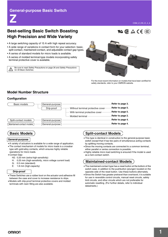
📄 Preview PAGE OF 28

Page 1 Text Content

General-purpose Basic Switch

CSM_Z_DS_E_4_6

Best-selling Basic Switch Boasting High Precision and Wide Variety A large switching capacity of 15 A with high repeat accuracy. A wide range of variations in contact form for your selection: basic, split-contact, maintained-contact, and adjustable contact gap types. A series of standard models for micro loads is available. A series of molded terminal-type models incorporating safety terminal protective cover is available.

Be sure to read Safety Precautions on page 26 and Safety Precautions for All Basic Switches.

For the most recent information on models that have been certified for safety standards, refer to your OMRON website.

Model Number Structure Configuration

Refer to page 3.

Basic models General-purpose

Refer to page 5.

Drip-proof Without terminal protective cover

Refer to page 5.

With terminal protective cover

Refer to page 2.

Molded terminal

Refer to page 4.

Split-contact models General-purpose

Refer to page 4.

Maintained-contact models General-purpose

Basic Models Split-contact Models This type is identical in construction to the general-purpose basic

General-purpose

switch except that it has two pairs of simultaneous acting contacts

A variety of actuators is available for a wide range of application. by splitting moving contacts. The contact mechanism of models for micro loads is a crossbar Since the moving contacts are connected to a common terminal, type with gold-alloy contacts, which ensures highly reliable either parallel or series connection is possible. operations for micro loads. Highly reliable micro load switching is ensured if the model is used Contact Gap: as a twin-contact switch. H2: 0.20 mm (extra-high-sensitivity) H: 0.25 mm (high-sensitivity, micro voltage current load)

Maintained-contact Models

G: 0.5 mm (standard) E: 1.8 mm (high-capacity) The maintained-contact type has a reset button at the bottom of the

switch case, in addition to the pushbutton (plunger) located on the

Drip-proof opposite side of the reset button. Use these buttons alternately.

Since the Switch has greater pretravel than overtravel, it is suitable

These Switches use a rubber boot on the actuator and adhesive fill

for use in reversible control circuits, manual reset circuits, safety

between the case and cover to increase resistance to drips.

limit circuits, and other circuits which are not preferable for

Models with drip-proof terminal protective covers and molded

automatic resetting. (For further details, refer to individual

terminals with resin filling are also available.

datasheets.)

Page Summary Contents For OMRON Basic Switch Z Z Data Sheet

Page 1 General-purpose Basic Switch CSM_Z_DS_E_4_6 Best-selling Basic Switch Boasting High Precision and Wide Variety A large switching capacity of 15 A with high repeat accuracy. A wide range of variations ...
Page 2 Model Number Legend Basic Models Standard Models (Drip-proof Type/Molded Terminals) Z-@@@@-@ Z-@55-M@@ @M (1)(2)(3)(4) (5) (1) (2)(3) (4) (1) Ratings (1) Drip-proof Type 0.1 A (micro load) (2) Lead Ou...
Page 3 Ordering Information Main Unit Basic Models (General-purpose) Extra-high Classification Standard High-sensitivity High-capacity Micro load sensitivity Actuator Contact gap G (0.5 mm) H (0.25 mm) H2 (0...
Page 4 Minimum Order Lot The following models are available at the minimum order lot specified below. Orders must be placed per lot. Classification Minimum Standard High-sensitivity order lot (pcs)Actuator S...
Page 5 Basic Models (Drip-proof Models ) Standard, Microload Classification Standard Micro load Contact gap G (0.5 mm) H (0.25 mm) Drip-proof terminal Not provided Provided Not provided protective cover Actu...
Page 6 Basic Models (Drip-proof Models ) High-sensitivity Minimum Order Lot Classification High-sensitivity The following models are available at the minimum order lot specified below. Contact gap H (0.25 mm...
Page 7 ur ab ili ty x1 pe ra tio ns Certified Standard Ratings Ask your OMRON representative for information on certified models. UL/CSA (General ratings only) TÜV (EN61058-1) Rated Rated Model Z-15 Z-10F Z-...
Page 8 Structure Basic Models Split-contact Models Contact Form (SPDT) Contact Form COM NC NOCOM Note: The Z-15GM is a reversible model and the NO and NC positions are NC reversed. Note: The NO and NC termin...
Page 9 Dimensions (Unit: mm) Mounting Use M4 screws with plane washers and spring washers to mount the When mounting the Switch to a panel, use a tightening torque of 2.94 Switch. Tighten each mounting screw...
Page 10 Short Spring Plunger 12.3 dia. Z-15GD-B Z-01HD-B 10 dia. PT 23.3±0.25 7.15 dia. Z-15HD-B Z-10FDY-B 12SR * 4.2 dia. hole+0.075 -0.025 Z-15ED-B 4.36 dia.+0.1 -0.05 25.4±0.1 * Plated iron plunger 49.2 Z-...
Page 11 Panel Mount Cross Roller Plunger Z-15GQ21-B Z-15EQ21-B 23.3±0.25 12.7 dia. × 4.8 *1 Z-15HQ21-B Z-15GQ21-B Z-15HQ21-B OF 2.45 to 3.43 N 1.96 to 2.79 N *2 RF min. 1.12 N 1.12 N PT max. 0.4 mm 0.3 mm 15....
Page 12 Low-force Hinge Lever t = 1 * Z-15GW4-B 26.2 63.5R 20.2 OP 16.9 OF max. 274 m N RF min. 34.3 m N PT max. 10 mm 4.2 dia. hole+0.075 -0.025 OT min. 5.6 mm 4.36 dia.+0.1 -0.05 MD max. 1.27 mm 25.4±0.1 OP...
Page 13 Short Hinge Cross Roller Lever 26.2 9.5 dia. × 4 Z-15GW49-B (plastic roller) Z-15GW54-B (Lever Length: 48.7R) * FP OP Z-15GW49-B Z-15GW54-B OF max. 1.67 N 0.98 N RF min. 0.41 N 0.22 N 9.2 OT min. 2.4 ...
Page 14 Basic Models (Drip-proof) without Terminal Protective Cover Terminals (Molded Terminals: Refer to page 21.) Without Terminal Protective Cover COM NO NC Three, M4 × 5.5 Terminal screws Note: With rever...
Page 15 Panel Mount Plunger 8.35 dia. PT 23.3±0.25 Z-15GQ55-B 11.9SR M12 × 1 *1 Mounting screw OP *2 4.2 dia. hole+0.075 -0.025 OF max. 5.30 N RF min. 1.12 N *416.3 16 dia. PT max. 1.8 mm OT min. 5.5 mm 9.2 M...
Page 16 Roller Leaf Spring 9.5 dia. × 4 Z-15GL255-B ±0.8 (plastic roller) 4.2 dia. hole+0.075 -0.025 OF max. 1.96 N OPFP RF min. 0.14 N OT *min. 1.6 mm MD max. 1.3 mm FP max. 31.8 mm OP 28.6±0.8 mm 4.36 dia.+...
Page 17 Hinge Roller Lever 9.5 dia. × 4 Z-15GW255-B (plastic roller) FP OP OF max. 1.27 N 9.2 RF min. 0.21 N 4.2+0.075 -0.025 OT min. 4 mm 4.2 dia. hole+0.075 -0.025 4.36 dia.+0.1 MD max. 1.6 mm 11.9 17.45±0....
Page 18 Flexible Rod (Coil Spring) Z-15GNJ55-B 6.1 dia. PT 3.2 dia. Nylon rod 30 Operating range *2 Rubber cap 12 dia. 23.3±0.25 OF max. 0.49 N (13.6) 4.2 dia. hole+0.075 -0.025 PT max. (20 mm) TT max. 40 mm ...
Page 19 Basic Models (Drip-proof) with Terminal Protective Cover Dimensions and Operating Characteristics Pin Plunger 6SR * 3.9 dia. PT 23.3±0.25 Z-15GA55-B5V OP 14.7 OF max. 2.45 to 4.22 N (11) RF min. 1.12 ...
Page 20 Long Hinge Lever Z-15GW44A55-B5V 4.9 20.2 OP 16.9 OF max. 0.88 N 4.2+0.075 -0.025 RF min. 0.14 N 19.2 OT min. 5.6 mm 4.36 dia.+0.1 MD max. 3.5 mm 4.2 dia. hole+0.075 -0.025 FP max. 33 mm OP 19±1.2 mm ...
Page 21 Basic Models (Drop-proof) with Modeled terminals Molded Terminals L/R Type (The following illustration is the R type.) D Type Size (mm) Size (mm) Lead wire Lead wire VSF VSF VCT VCT Lead Wire Specific...
Page 22 Accessories (Order Separately) A Terminal Protective Cover, Actuators, and a Separator are available. Drip-proof Terminal Cover (Order Separately) The Drip-proof Terminal Protective Cover is provided ...
Page 23 Dimensions (Unit: mm) Terminal Covers AP-A AP-B Soldering Terminal Use Screw Terminal Use (Phenol Resin) (Phenol Resin) Note: The Cover has five thin, easy-to-separate Note: The Cover has six thin, ea...
Page 24 Actuators (Sold Separately) A Switch can be actuated by a cam or an appropriate object, in which case, use one of the following Actuators according to the application. Ordering Information Actuator Ap...
Page 25 Medium Panel Mount Plunger 7.9 dia. PT 23.3 ZAQ-2 *1 M12 × 1 mounting screw ZAQ-2 2 t × 14 width across Z-15E-B X-10G-B flats OF max. 8.34 N 5.39 N RF min. 1.12 N 1.12 N PT max. 0.8 mm 1 mm OT min. 4....
Page 26 Safety Precautions Refer to Safety Precautions for All Basic Switches. Precautions for Safe Use Incorrect Correct Separate the installation lo- cation from Terminal Connection heat sources. When solde...
Page 27 ol ta ge 2. If the switching speed is extremely fast, switching shock may Models with Drip-proof Terminal Cover (Z-@A55-B5V) damage the Switch prematurely. If the switching frequency is too Wiring hig...
Page 28 Terms and Conditions Agreement Read and understand this catalog. Please read and understand this catalog before purchasing the products. Please consult your OMRON representative if you have any questi...

Manual Details

Brand Omron
Pages 28
File Size 7.15 MB
Published June 05, 2026
78 views

Enter the captcha to get the download link:

captcha

Frequently Asked Questions

What is the primary function of a maintained-contact model?

It features both a reset button and a pushbutton, making it suitable for reversible control circuits or manual reset circuits.

How do I guarantee reliable switching when dealing with micro loads?

Utilize models designed for micro loads that incorporate gold-alloy contacts to ensure highly dependable parallel or series operation.

What safeguards are required before using this switch in any system?

Never use the product for applications involving serious risk to life or property without ensuring the entire system has been correctly addressed and rated.

Are there options if I need the device protected from moisture?

Yes, drip-proof models are available, which can be supplied either with or without terminal protective covers.