# A B C D E F G H I J K L M N O P Q R S T U V W X Y Z

National Semiconductor LM5010A High Voltage 1A Step Down Switching Regulator Data Sheet User Manual

Summary

The LM5010A is a high-performance step-down switching regulator designed for efficient power conversion across a broad input range of 6V to 75V. This robust single component features an integrated N-Channel Buck Switch, supporting stable output up to 1A load current. The manual serves as a comprehensive technical guide for engineers, detailing the product’s full specifications, pin assignments, connection diagrams, and advanced features like programmable switching frequency and fast transient response. It is ideally suited for use in demanding industrial applications, including power supplies for automotive electronics and telecommunications infrastructure.
📄 Preview 📖 Table of Contents Contents PAGE OF 18

Page 1 Text Content

ig lta te itc in la to

January 25, 2008

LM5010A High Voltage 1A Step Down Switching Regulator General Description Features The LM5010A Step Down Switching Regulator is an en- Wide 6V to 75V Input Voltage Range hanced version of the LM5010 with the input operating range

Valley Current Limiting At 1.25A

extended to 6V minimum. The LM5010A features all the func-

Programmable Switching Frequency Up To 1 MHz

tions needed to implement a low cost, efficient, buck regulator

Integrated 80V N-Channel Buck Switch

capable of supplying in excess of 1A load current. This high

voltage regulator integrates an N-Channel Buck Switch, and Integrated High Voltage Bias Regulator

is available in thermally enhanced LLP-10 and TSSOP-14EP No Loop Compensation Required packages. The constant on-time regulation scheme requires

Ultra-Fast Transient Response

no loop compensation resulting in fast load transient re-

Nearly Constant Operating Frequency With Line and Load

sponse and simplified circuit implementation. The operating

Variations

frequency remains constant with line and load variations due

Adjustable Output Voltage

to the inverse relationship between the input voltage and the

on-time. The valley current limit detection is set at 1.25A. Ad- 2.5V, ±2% Feedback Reference

ditional features include: VCC under-voltage lock-out, thermal Programmable Soft-Start shutdown, gate drive under-voltage lock-out, and maximum

Thermal shutdown

duty cycle limiter.

Typical Applications Non-Isolated Telecommunications Regulator Secondary Side Post Regulator Power Supply for Automotive Electronics

Package LLP-10 (4 mm x 4 mm) TSSOP-14EP Both Packages Have Exposed Thermal Pad For Improved Heat Dissipation

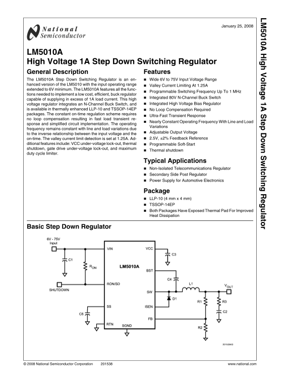
Basic Step Down Regulator

© 2008 National Semiconductor Corporation www.national.com

Page Summary Contents For National Semiconductor LM5010A High Voltage 1A Step Down Switching Regulator Data Sheet User Manual

Page 1 ig lta te itc in la to January 25, 2008 LM5010A High Voltage 1A Step Down Switching Regulator General Description Features The LM5010A Step Down Switching Regulator is an en- Wide 6V to 75V Input Volt...
Page 2 Connection Diagrams Ordering Information Order Number Package Type NSC Package Junction Temperature Range Supplied As Drawing LM5010ASD LLP-10 (4x4) SDC10A −40°C to + 125°C 1000 Units on Tape and Reel...
Page 3 Pin Descriptions Pin Number Name Description Application Information LLP-10 TSSOP-14 SW Switching Node Internally connected to the buck switch source. Connect to the inductor, free-wheeling diode, and...
Page 4 VIN to SW 76V Absolute Maximum Ratings (Note 1) All Other Inputs to RTN -0.3V to 7V If Military/Aerospace specified devices are required, ESD Rating (Note 2) please contact the National Semiconductor ...
Page 5 Symbol Parameter Conditions Min Typ Max Units Off Timer t OFF Minimum Off-time ns Regulation and Over-Voltage Comparators (FB Pin) VREF FB regulation threshold TJ ≤ 125°C 2.445 2.50 2.550 TJ ≤ 150°C F...
Page 6 Typical Performance Characteristics VCC vs VIN VCC vs ICC ICC vs Externally Applied VCC On-Time vs VIN and RON Voltage at RON/SD Pin IIN vs VIN www.national.com
Page 7 Block Diagram www.national.com
Page 8 FIGURE 1. Startup Sequence suited for 48V telecom applications, as well as the 42V auto- Functional Description motive power bus. Features include: Thermal shutdown, VCC The LM5010A Step Down Switchin...
Page 9 capacitor’s ESR is insufficient additional series resistance Start-Up Bias Regulator (VCC) may be required (R3 in the Block Diagram). A high voltage bias regulator is integrated within the The LM5010A...
Page 10 put voltage, or the output load, changes suddenly. The buck the minimum off-time of the LM5010A (260 ns, ±15%). The switch remains off until the voltage at FB falls below 2.5V. fixed off-time limits t...
Page 11 FIGURE 4. Inductor Current - Current Limit Operation N - Channel Buck Switch and Driver Applications Information The LM5010A integrates an N-Channel buck switch and as- EXTERNAL COMPONENTS sociated fl...
Page 12 FIGURE 5. Inductor Current To keep the circuit in continuous conduction mode, the max- ue (IPK+), then drops to zero at turn-off. The average current imum allowed ripple current is twice the minimum l...
Page 13 C3: The capacitor at the VCC pin provides noise filtering and For a 5 ms softstart time, C6 calculates to 0.022 µF. stability, prevents false triggering of the VCC UVLO at the buck D1: A Schottky diod...
Page 14 Item Description Value C1 Ceramic Capacitor (2) 2.2 µF, 100V C2 Ceramic Capacitor 22 µF, 16V C3 Ceramic Capacitor 0.47 µF, 16V C4, C6 Ceramic Capacitor 0.022 µF, 16V C5 Ceramic Capacitor 0.1 µF, 100V ...
Page 15 1000 p F capacitor at Cff and reducing R3 to 0.75Ω, the where IOR(max) is calculated using Equation 12. The inductor VOUT ripple was reduced by 50%, ranging from 25 m Vp-p to L1 and diode D1 must be r...
Page 16 Physical Dimensions inches (millimeters) unless otherwise noted 14-Lead TSSOP Package NS Package Number MXA14A 10-Lead LLP Package NS Package Number SDC10A www.national.com
Page 17 Notes www.national.com
Page 18 ig lt te it in la to Notes For more National Semiconductor product information and proven design tools, visit the following Web sites at: Products Design Support Amplifiers www.national.com/amplifiers...

Manual Details

Brand National
Pages 18
File Size 399.07 KB
Published June 01, 2026
80 views

Enter the captcha to get the download link:

captcha

Frequently Asked Questions

What is the minimum input voltage range for the LM5010A regulator?

The nominal input range is 6V to 75V.

Does the device require loop compensation for stable operation?

No, the constant on-time regulation scheme requires no loop compensation.

What are the recommended packages for heat dissipation?

Both the LLP-10 and TSSOP-14EP packages have exposed thermal pads designed for improved heat dissipation.

At what level does the device shut off due to overcurrent?

The valley current limit detection is set at 1.25A (typical).