NATIONAL SEMICONDUCTOR LM1815 Adaptive Variable Reluctance Sensor Amplifier User Manual
Summary
Elevate your motor control and position sensing systems with this adaptive sense amplifier. This robust gating circuit is designed for handling variable reluctance signals across diverse operating speeds, utilizing adaptive hysteresis for consistent performance whether measuring high-speed or low-speed rotation. It supports single supply operation from 2V to 12V. The accompanying manual provides comprehensive technical details, including operational modes, electrical characteristics, and detailed application guides, making it the essential resource for engineers designing robust sensing solutions for tachometers and motion control within engine testing systems.
Page 1 Text Content
April
LM daptive Variable eluctance ensor plifier
LM1815 Adaptive Variable Reluctance Sensor Amplifier General Description Features
The LM1815 is an adaptive sense amplifier and default Adaptive hysteresis gating circuit for motor control applications. The sense am- Single supply operation
plifier provides one-shot pulse output whose leading edge Ground referenced input coincides with the negative-going zero crossing of ground
True zero crossing timing reference
referenced input signal such as from variable reluctance
Operates from 2V to 12V supply voltage
magnetic pick-up coil.
Handles inputs from m VP-P to over 120VP-P with
In normal operation, this timing reference signal is pro-
external resistor
cessed (delayed) externally and returned to the LM1815.
CMOS compatible logic
Logic input is then able to select either the timing reference or the processed signal for transmission to the output driver
Applications
stage.
Position sensing with notched wheels
The adaptive sense amplifier operates with positive-going
Zero crossing switch
threshold which is derived by peak detecting the incoming
signal and dividing this down. Thus the input hysteresis Motor speed control varies with input signal amplitude. This enables the circuit to Tachometer
sense in situations where the high speed noise is greater Engine testing than the low speed signal amplitude. Minimum input signal is 150m VP-P.
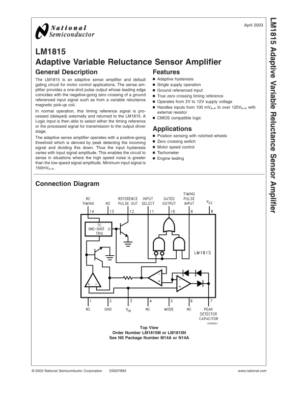
Connection Diagram
Order Number LM1815M or LM1815N See NS Package Number M14A or N14A
National Semiconductor Corporation DS007893 www.national.com
Page Summary Contents For NATIONAL SEMICONDUCTOR LM1815 Adaptive Variable Reluctance Sensor Amplifier User Manual
Manual Details
| Brand | National |
|---|---|
| Pages | 11 |
| File Size | 372.41 KB |
| Published | June 15, 2026 |
Enter the captcha to get the download link:

Frequently Asked Questions
What is the operational voltage range for this amplifier?
It operates from a 2V to 12V supply voltage.
How does the input hysteresis vary in normal operation?
The hysteresis varies with the input signal amplitude because it uses an adaptive sense amplifier which derives its threshold by peak detecting and dividing the incoming signal.
What are the minimum requirements for a detectable motor speed signal?
The circuit requires a minimum input signal of 150mV P-P (in Signal Adaptive Input Arming Mode).
What is the maximum temperature junction rating?
The Junction Temperature can reach +150˚C.
Can this device select between timing references or processed signals?
Yes, a CMOS compatible logic input allows selecting either the timing reference or the processed signal for transmission to the output driver.