# A B C D E F G H I J K L M N O P Q R S T U V W X Y Z

NATIONAL SEMICONDUCTOR LM1575 LM2575 LM2575HV Owner's Manual

Summary

This technical resource details the LM1575/LM2575/LM2575HV series, highly efficient simple switcher step-down voltage regulators (buck converters). Engineered for diverse power supply applications, these regulators provide stable, adjustable output voltages (3.3V to 15V) and are capable of handling 1A loads. The manual provides comprehensive details on features—such as high efficiency, wide input ranges, internal compensation, and various physical packages—making it an essential guide for electrical engineers designing compact, reliable switching power solutions.
📄 Preview PAGE OF 28

Page 1 Text Content

/L /L rie IM IT te -D lta la to

April 2007

LM1575/LM2575/LM2575HV SIMPLE SWITCHER® 1A Step-Down Voltage Regulator General Description Features The LM2575 series of regulators are monolithic integrated 3.3V, 5V, 12V, 15V, and adjustable output versions circuits that provide all the active functions for a step-down

Adjustable version output voltage range,

(buck) switching regulator, capable of driving a 1A load with

1.23V to 37V (57V for HV version) ±4% max over

excellent line and load regulation. These devices are avail-

line and load conditions

able in fixed output voltages of 3.3V, 5V, 12V, 15V, and an

Guaranteed 1A output current

adjustable output version.

Wide input voltage range, 40V up to 60V for HV version

Requiring a minimum number of external components, these

Requires only 4 external components

regulators are simple to use and include internal frequency

compensation and a fixed-frequency oscillator. 52 k Hz fixed frequency internal oscillator The LM2575 series offers a high-efficiency replacement for TTL shutdown capability, low power standby mode

popular three-terminal linear regulators. It substantially re- High efficiency duces the size of the heat sink, and in many cases no heat

Uses readily available standard inductors

sink is required.

Thermal shutdown and current limit protection

A standard series of inductors optimized for use with the

P+ Product Enhancement tested

LM2575 are available from several different manufacturers. This feature greatly simplifies the design of switch-mode pow-

er supplies. Applications

Other features include a guaranteed ±4% tolerance on output Simple high-efficiency step-down (buck) regulator voltage within specified input voltages and output load con-

Efficient pre-regulator for linear regulators

ditions, and ±10% on the oscillator frequency. External shut-

On-card switching regulators

down is included, featuring 50 μA (typical) standby current.

Positive to negative converter (Buck-Boost)

The output switch includes cycle-by-cycle current limiting, as well as thermal shutdown for full protection under fault con- ditions.

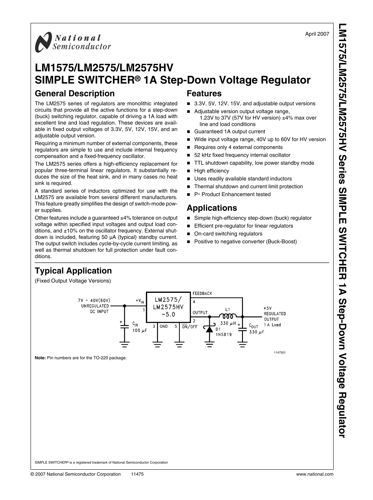
Typical Application (Fixed Output Voltage Versions)

Note: Pin numbers are for the TO-220 package.

SIMPLE SWITCHER® is a registered trademark of National Semiconductor Corporation

© 2007 National Semiconductor Corporation www.national.com

Page Summary Contents For NATIONAL SEMICONDUCTOR LM1575 LM2575 LM2575HV Owner's Manual

Page 1 /L /L rie IM IT te -D lta la to April 2007 LM1575/LM2575/LM2575HV SIMPLE SWITCHER® 1A Step-Down Voltage Regulator General Description Features The LM2575 series of regulators are monolithic integrated...
Page 2 Block Diagram and Typical Application 3.3V, R2 = 1.7k 5V, R2 = 3.1k 12V, R2 = 8.84k 15V, R2 = 11.3k For ADJ. Version R1 = Open, R2 = 0Ω Note: Pin numbers are for the TO-220 package. FIGURE 1. www.nati...
Page 3 Connection Diagrams (XX indicates output voltage option. See Ordering Information table for complete part number.) Straight Leads Bent, Staggered Leads 5–Lead TO-220 (T) 5-Lead TO-220 (T) Side View LM...
Page 4 Ordering Information Package NSC Standard High Temperature Type Package Voltage Rating Voltage Rating Range Number (40V) (60V) 5-Lead TO-220 T05A LM2575T-3.3 LM2575HVT-3.3 Straight Leads LM2575T-5.0 L...
Page 5 Minimum ESD Rating Absolute Maximum Ratings (Note 1) If Military/Aerospace specified devices are required, Lead Temperature please contact the National Semiconductor Sales Office/ Distributors for ava...
Page 6 Symbol Parameter Conditions Typ LM1575-5.0 LM2575-5.0 Units (Limits) LM2575HV-5.0 Limit Limit (Note 2) (Note 3) VOUT Output Voltage 0.2A ≤ ILOAD ≤ 1A, 5.0 LM2575HV 8V ≤ VIN ≤ 60V 4.850/4.800 4.800/4.7...
Page 7 LM1575-ADJ, LM2575-ADJ, LM2575HV-ADJ Electrical Characteristics Specifications with standard type face are for TJ= 25°C, and those with boldface type apply over full Operating Temperature Range. Symbo...
Page 8 Symbol Parameter Conditions Typ LM1575-XX LM2575-XX Units (Limits) LM2575HV-XX Limit Limit (Note 2) (Note 3) θJA Thermal Resistance T Package, Junction to Ambient (Note 9) θJA T Package, Junction to A...
Page 9 Typical Performance Characteristics (Circuit of Figure 2) Normalized Output Voltage Line Regulation Dropout Voltage Current Limit Quiescent Current Standby Quiescent Current www.national.com
Page 10 Oscillator Frequency Switch Saturation Voltage Efficiency Minimum Operating Voltage Quiescent Current Feedback Voltage vs Duty Cycle vs Duty Cycle www.national.com
Page 11 /L /L Feedback Pin Current Maximum Power Dissipation (TO-263) (See (Note 12)) Switching Waveforms Load Transient Response VOUT = 5V A: Output Pin Voltage, 10V/div B: Output Pin Current, 1A/div C: Indu...
Page 12 by heavy lines should be kept as short as possible. Single- /L /L Test Circuit and Layout Guidelines point grounding (as indicated) or ground plane construction As in any switching regulator, layout i...
Page 13 LM2575 Series Buck Regulator Design Procedure PROCEDURE (Fixed Output Voltage Versions) EXAMPLE (Fixed Output Voltage Versions) Given: Given: VOUT = Regulated Output Voltage (3.3V, 5V, 12V, or 15V) VO...
Page 14 Inductor Value Selection Guides (For Continuous Mode Operation) FIGURE 5. LM2575(HV)-12 FIGURE 3. LM2575(HV)-3.3 FIGURE 6. LM2575(HV)-15 FIGURE 4. LM2575(HV)-5.0 FIGURE 7. LM2575(HV)-ADJ www.national....
Page 15 /L /L PROCEDURE (Adjustable Output Voltage Versions) EXAMPLE (Adjustable Output Voltage Versions) Given: Given: VOUT = Regulated Output Voltage VOUT = 10V VIN(Max) = Maximum Input Voltage VIN(Max) = 2...
Page 16 PROCEDURE (Adjustable Output Voltage Versions) EXAMPLE (Adjustable Output Voltage Versions) 4. Catch Diode Selection (D1) 4. Catch Diode Selection (D1) A. The catch-diode current rating must be at lea...
Page 17 VR Schottky Fast Recovery 20V 1N5817 1N5820 MBR120P MBR320 SR102 SR302 30V 1N5818 1N5821 MBR130P MBR330 The following The following 11DQ03 31DQ03 diodes are all diodes are all rated to 100V rated to 1...
Page 18 circuits, or can give incorrect scope readings because of in- /L /L Application Hints duced voltages in the scope probe. INPUT CAPACITOR (CIN) The inductors listed in the selection chart include ferri...
Page 19 be used in parallel with aluminum electrolytics, with the tan- /L /L With the N or M packages, all the pins labeled ground, power talum making up 10% or 20% of the total capacitance. ground, or signal...
Page 20 tance numbers as low as 40°C/W for the SO package, and would allow the input voltage to rise to a high enough level /L /L 30°C/W for the N package can be realized with a carefully before the switcher ...
Page 21 NEGATIVE BOOST REGULATOR /L /L Another variation on the buck-boost topology is the negative boost configuration. The circuit in Figure 11 accepts an input voltage ranging from −5V to −12V and provides...
Page 22 Note: Pin numbers are for the TO-220 package. FIGURE 15. 1.2V to 55V Adjustable 1A Power Supply with Low Output Ripple www.national.com
Page 23 /L /L EQUIVALENT SERIES INDUCTANCE (ESL) Definition of Terms The pure inductance component of a capacitor (see Figure BUCK REGULATOR 16). The amount of inductance is determined to a large extent on th...
Page 24 Physical Dimensions inches (millimeters) unless otherwise noted 16-Lead Ceramic Dual-in-Line (J) Order Number LM1575J-3.3/883, LM1575J-5.0/883, LM1575J-12/883, LM1575J-15/883, or LM1575J-ADJ/883 NS Pa...
Page 25 16-Lead Molded DIP (N) Order Number LM2575N-5.0, LM2575HVN-5.0, LM2575N-12, LM2575HVN-12, LM2575N-15, LM2575HVN-15, LM2575N-ADJ or LM2575HVN-ADJ NS Package Number N16A 5-Lead TO-220 (T) Order Number L...
Page 26 TO-263, Molded, 5-Lead Surface Mount Order Number LM2575S-3.3, LM2575HVS-3.3, LM2575S-5.0, LM2575HVS-5.0, LM2575S-12, LM2575HVS-12, LM2575S-15, LM2575HVS-15, LM2575S-ADJ or LM2575HVS-ADJ NS Package Nu...
Page 27 Bent, Staggered 5-Lead TO-220 (T) Order Number LM2575T-3.3 Flow LB03, LM2575HVT-3.3 Flow LB03, LM2575T-5.0 Flow LB03, LM2575HVT-5.0 Flow LB03, LM2575T-12 Flow LB03, LM2575HVT-12 Flow LB03, LM2575T-15 ...
Page 28 /L /L ri IM IT te -D lt la to Notes THE CONTENTS OF THIS DOCUMENT ARE PROVIDED IN CONNECTION WITH NATIONAL SEMICONDUCTOR CORPORATION (“NATIONAL”) PRODUCTS. NATIONAL MAKES NO REPRESENTATIONS OR WARRANT...

Manual Details

Brand National
Pages 28
File Size 856.67 KB
Published July 16, 2026
0 views

Enter the captcha to get the download link:

captcha

Frequently Asked Questions

What is the primary advantage of using this step-down regulator over traditional linear regulators?

It is a high-efficiency (buck) switch-mode regulator that substantially reduces the size required for heat sinks, and in many cases, no heat sink is needed.

What are the available fixed output voltages if I do not need an adjustable version?

Fixed versions are typically available at 3.3V, 5V, 12V, and 15V.

What types of protection does the regulator offer to prevent circuit failure?

It includes thermal shutdown, current limit protection, và TTL shutdown capability for full protection under fault conditions.

How many external components are required for implementation?

These regulators minimize complexity and require only a minimum number of four external components, including standard available inductors.