National Semiconductor DM54191 DM74191 Data Handbook
Summary
This synchronous, reversible 4-Bit Binary Counter is a versatile integrated circuit designed for reliable timing applications. It functions as an Up/Down counter with full mode control, featuring low ripple timing clocks and high ease of cascading into larger n-bit systems. This manual provides comprehensive technical documentation, covering detailed electrical characteristics, maximum ratings, operating conditions, and optimal application guidelines necessary for hardware designers needing a stable, programmable counting solution.
Page 1 Text Content
ro -B it in ry te ith tro
54191/DM54191/DM74191 Synchronous Up/Down 4-Bit Binary Counter with Mode Control General Description
This circuit is synchronous, reversible, up/down counter. Two outputs have been made available to perform the cas- The is 4-bit binary counter. Synchronous operation is cading function: ripple clock and maximum/minimum count. provided by having all flip-flops clocked simultaneously so The latter output produces high-level output pulse with that the outputs change simultaneously when so instructed duration approximately equal to one complete cycle of the by the steering logic. This mode of operation eliminates the clock when the counter overflows or underflows. The ripple output counting spikes normally associated with asynchro- clock output produces low-level output pulse equal in nous (ripple clock) counters. width to the low-level portion of the clock input when an overflow or underflow condition exists. The counters can be
The outputs of the four master-slave flip-flops are triggered
easily cascaded by feeding the ripple clock output to the
on low-to-high level transition of the clock input, if the
enable input of the succeeding counter if parallel clocking is
enable input is low. high at the enable input inhibits count-
used, or to the clock input if parallel enabling is used. The
ing. Level changes at either the enable input or the down/
maximum/minimum count output can be used to accom-
up input should be made only when the clock input is high.
plish look-ahead for high-speed operation.
The direction of the count is determined by the level of the down/up input. When low, the counter counts up and when
high, it counts down. Features This counter is fully programmable; that is, the outputs may Single down/up count control line be preset to either level by placing low on the load input Count enable control input
and entering the desired data at the data inputs. The output Ripple clock output for cascading will change independent of the level of the clock input. This Asynchronously presettable with load control feature allows the counters to be used as modulo-N dividers
Parallel outputs
by simply modifying the count length with the preset inputs.
Cascadable for n-bit applications
The clock, down/up, and load inputs are buffered to lower
Alternate Military/Aerospace device (54191) is avail-
the drive requirement; which significantly reduces the num-
able. Contact National Semiconductor Sales Office/
ber of clock drivers, etc., required for long parallel words.
Distributor for specifications.
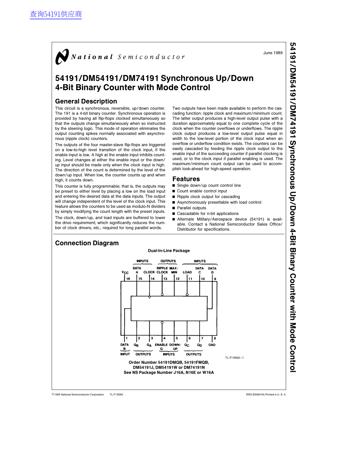
Connection Diagram
Dual-In-Line Package
TL/F/6562–1
Order Number 54191DMQB, 54191FMQB, DM54191J, DM54191W or DM74191N See NS Package Number J16A, N16E or W16A
C1995 National Semiconductor Corporation TL/F/6562 RRD-B30M105/Printed in U. S. A.
Page Summary Contents For National Semiconductor DM54191 DM74191 Data Handbook
Manual Details
| Brand | National |
|---|---|
| Pages | 6 |
| File Size | 130.65 KB |
| Published | July 22, 2026 |
Enter the captcha to get the download link:

Frequently Asked Questions
How can I change the direction of the count cycle?
The direction is set by the down/up input: when low, it counts up; when high, it counts down.
What range of temperatures should I consider for operation?
DM54191 operates from 0°C to 125°C, while DM74191 is recommended for 0°C to 70°C.
How can this counter be used to count more than 4 bits?
It is designed to be cascaded using the ripple clock output for n-bit applications.
What is the required method for manually setting a desired value?
The counter can be pre-set by placing a low on the load input and entering the desired data at the data inputs.