LM75 Data Handbook from NATIONAL SEMICONDUCTOR
Summary
This technical document introduces the LM75 Digital Temperature Sensor and Thermal Watchdog, an industry-leading component for sophisticated thermal management. Utilizing a low-power two-wire I²C interface, this sensor accurately monitors temperatures from -55°C to 125°C while providing programmable over-temperature safety shutoff (OS). The manual details the device specifications, connection diagrams, operating parameters, and integration methods crucial for engineers. It is essential reading for developers building reliable systems like personal computers, office electronics, and test equipment requiring precise digital temperature monitoring and hardware protection.
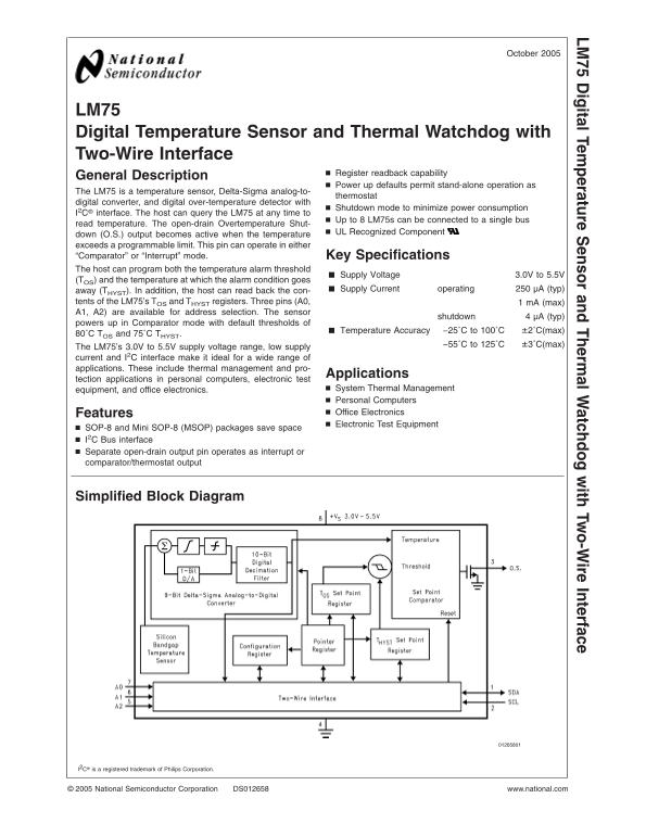
Page 1 Text Content
October
LM igital Tem perature ensor and Therm al W atchdog ith Tw o-W ire Interface
LM75 Digital Temperature Sensor and Thermal Watchdog with Two-Wire Interface
Register readback capability
General Description
Power up defaults permit stand-alone operation as
The LM75 is temperature sensor, Delta-Sigma analog-to-
thermostat
digital converter, and digital over-temperature detector with
Shutdown mode to minimize power consumption
I2C® interface. The host can query the LM75 at any time to
Up to LM75s can be connected to single bus
read temperature. The open-drain Overtemperature Shut-
UL Recognized Component
down (O.S.) output becomes active when the temperature exceeds programmable limit. This pin can operate in either “Comparator” or “Interrupt” mode. Key Specifications The host can program both the temperature alarm threshold
Supply Voltage 3.0V to 5.5V
(TOS) and the temperature at which the alarm condition goes
away (THYST). In addition, the host can read the con- Supply Current operating µA (typ)
tents of the LM75’s TOS and THYST registers. Three pins (A0, m A (max)
A1, A2) are available for address selection. The sensor
shutdown µA (typ)
powers up in Comparator mode with default thresholds of
Temperature Accuracy −25˚C to 100˚C ±2˚C(max)
80˚C TOS and 75˚C THYST.
−55˚C to 125˚C ±3˚C(max)
The LM75’s 3.0V to 5.5V supply voltage range, low supply
current and I2C interface make it ideal for wide range of
applications. These include thermal management and pro-
Applications
tection applications in personal computers, electronic test
equipment, and office electronics. System Thermal Management Personal Computers Features Office Electronics Electronic Test Equipment
SOP-8 and Mini SOP-8 (MSOP) packages save space I2C Bus interface Separate open-drain output pin operates as interrupt or comparator/thermostat output
Simplified Block Diagram
I2C® is registered trademark of Philips Corporation.
National Semiconductor Corporation DS012658 www.national.com
Page Summary Contents For LM75 Data Handbook from NATIONAL SEMICONDUCTOR
Manual Details
| Brand | National |
|---|---|
| Pages | 18 |
| File Size | 737.56 KB |
| Published | May 29, 2026 |
Enter the captcha to get the download link:

Frequently Asked Questions
What is the recommended operating voltage range for the LM75 sensor?
The general supply voltage is 3.0V to 5.5V, making it suitable for various electronics applications.
How many sensors can be connected on a single bus?
Up to 8 LM75s can be connected and read via the I2C interface.
What happens when temperatures exceed programmable limits?
The Open-Drain Overtemperature Shutdown (O.S.) output activates, indicating overheating to the host system.
Can I customize the temperature alarm thresholds?
Yes, the host can program both the temperature alarm threshold and the condition for the alarm onset.