National Semiconductor DM5404 DM7404 Hex Inverting Gates Data Sheet - Specifications User Guide Manual
Summary
These Hex Inverting Gates are integrated circuits designed for robust digital logic applications, providing six independent gates each performing a reliable INVERT function. The comprehensive manual serves as a technical resource for engineers, detailing crucial specifications such as operating voltage ranges, electrical characteristics across varying temperatures, timing parameters, and compatibility with various package styles (Ceramic/Molded). Use this guide to ensure proper integration into your electronic circuit designs, covering both general use and specialized military/aerospace requirements.
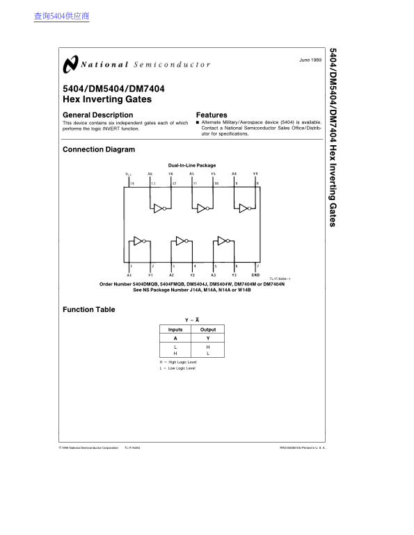
Page 1 Text Content
In rtin te
5404/DM5404/DM7404 Hex Inverting Gates General Description Features
This device contains six independent gates each of which Alternate Military/Aerospace device (5404) is available. performs the logic INVERT function. Contact National Semiconductor Sales Office/Distrib- utor for specifications.
Connection Diagram
Dual-In-Line Package
TL/F/6494–1
Order Number 5404DMQB, 5404FMQB, DM5404J, DM5404W, DM7404M or DM7404N
See NS Package Number J14A, M14A, N14A or W14B
Function Table
Inputs Output
High Logic Level Low Logic Level
C1995 National Semiconductor Corporation TL/F/6494 RRD-B30M105/Printed in U. S. A.
Page Summary Contents For National Semiconductor DM5404 DM7404 Hex Inverting Gates Data Sheet - Specifications User Guide Manual
Manual Details
| Brand | National |
|---|---|
| Pages | 6 |
| File Size | 108.02 KB |
| Published | June 16, 2026 |
Enter the captcha to get the download link:

Frequently Asked Questions
What is the difference in operating temperature for DM54 vs DM74 models?
The DM54 series operates from -55°C to 125°C, while the DM74 series handles a range of 0°C to 70°C.
What are the required supply voltage parameters?
The recommended operating supply voltage ranges from 4.5V (min) to 5.5V (max).
How do I handle short circuit conditions with this chip?
As per Note 2, ensure that not more than one output is shorted at a time when calculating current limits.
What are the physical package options and corresponding order numbers?
Packages include J14A (DM5404DMQB) and M14A (DM7404M), among others, depending on ceramic or molded material.