Motorola MCR106 Series Data Handbook / Manual
Summary
These Technical Data Sheets provide comprehensive specifications for robust SCR Thyristor devices, ideal for critical power control and switching applications. The manual details key electrical parameters (blocking voltage, current handling), maximum ratings, thermal characteristics, and safe operating limits across demanding temperature ranges. It is designed for engineers and industry professionals who require reliable semiconductor components for process controls, industrial automation, and warning systems where high operational integrity is crucial.
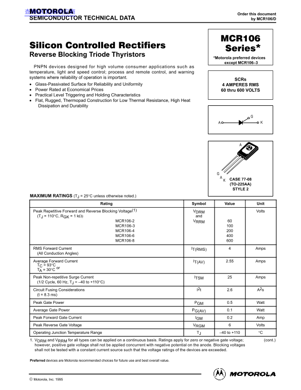
Page 1 Text Content
查询MCR106供应商
Order this document
SEMICONDUCTOR TECHNICAL DATA by MCR106/D
Reverse Blocking Triode Thyristors
*Motorola preferred devices except MCR106–3
PNPN devices designed for high volume consumer applications such as temperature, light and speed control; process and remote control, and warning systems where reliability of operation is important.
Glass-Passivated Surface for Reliability and Uniformity 4 AMPERES RMS Power Rated at Economical Prices 60 thru 600 VOLTS Practical Level Triggering and Holding Characteristics Flat, Rugged, Thermopad Construction for Low Thermal Resistance, High Heat Dissipation and Durability
CASE 77-08 (TO-225AA) STYLE 2
MAXIMUM RATINGS (TJ = 25°C unless otherwise noted.)
Rating Symbol Value Unit
Peak Repetitive Forward and Reverse Blocking Voltage(1) VDRM Volts
(TJ = 110°C, RGK = 1 kΩ) and MCR106-2 VRRM
MCR106-3 MCR106-4 MCR106-6 MCR106-8
RMS Forward Current IT(RMS) Amps (All Conduction Angles) Average Forward Current IT(AV) 2.55 Amps TC = 93°C
TA = 30°C Peak Non-repetitive Surge Current ITSM Amps (1/2 Cycle, 60 Hz, TJ = –40 to +110°C) Circuit Fusing Considerations I2t 2.6 A2s (t = 8.3 ms) Peak Gate Power PGM 0.5 Watt Average Gate Power PG(AV) 0.1 Watt Peak Forward Gate Current IGM 0.2 Amp Peak Reverse Gate Voltage VRGM Volts Operating Junction Temperature Range TJ –40 to +110 °C 1. VDRM and VRRM for all types can be applied on a continuous basis. Ratings apply for zero or negative gate voltage; (cont.) however, positive gate voltage shall not be applied concurrent with negative potential on the anode. Blocking voltages shall not be tested with a constant current source such that the voltage ratings of the devices are exceeded.
Preferred devices are Motorola recommended choices for future use and best overall value.
1Motorola Thyristor Device Data
Motorola, Inc. 1995
Page Summary Contents For Motorola MCR106 Series Data Handbook / Manual
Manual Details
| Brand | Motorola |
|---|---|
| Pages | 4 |
| File Size | 94.63 KB |
| Published | June 01, 2026 |
Enter the captcha to get the download link:

Frequently Asked Questions
What is the maximum continuous junction temperature operating range?
The operating junction temperature range (Tj) is from –40°C to +110°C.
What precautions are needed when soldering or mounting the device?
For soldering, temperatures must not exceed +200°C. For optimal results, using an activated flux is recommended.
Can positive and negative gate voltages be applied concurrently?
No; positive gate voltage shall not be applied concurrently with a negative potential on the anode.
What are the minimum requirements for reliable usage?
All operating parameters, including 'Typical' values, must be validated by the customer’s technical experts for each specific application.