MOTOROLA MCR08BT1 Series Data Manual
Summary
Reliable Triode Thyristors engineered for consumer-level power management applications. Designed in a compact surface mount package, these SCRs are ideal for precise operation in motor control, relay drivers, and lamp switching circuits across varying voltage ranges. This technical document provides comprehensive specifications, including detailed electrical characteristics, thermal derating curves, and mounting guidelines necessary for advanced circuit design. It is essential reading for engineers selecting power semiconductors for stringent reliability requirements.
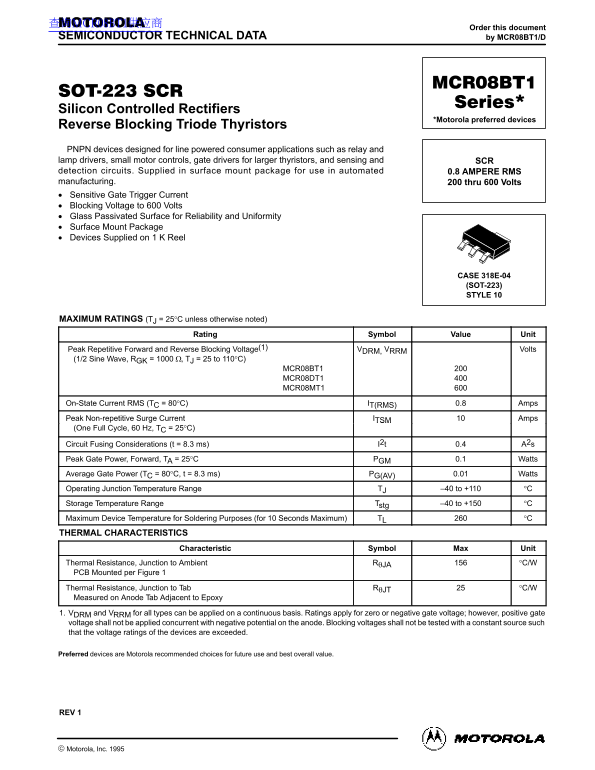
Page 1 Text Content
查询MCR08BT1供应商
Order this document
SEMICONDUCTOR TECHNICAL DATA by MCR08BT1/D
Silicon Controlled Rectifiers
*Motorola preferred devices
Reverse Blocking Triode Thyristors PNPN devices designed for line powered consumer applications such as relay and lamp drivers, small motor controls, gate drivers for larger thyristors, and sensing and SCR detection circuits. Supplied in surface mount package for use in automated 0.8 AMPERE RMS manufacturing. 200 thru 600 Volts Sensitive Gate Trigger Current Blocking Voltage to 600 Volts Glass Passivated Surface for Reliability and Uniformity Surface Mount Package Devices Supplied on 1 K Reel
CASE 318E-04 (SOT-223) STYLE 10
MAXIMUM RATINGS (TJ = 25°C unless otherwise noted)
Rating Symbol Value Unit
Peak Repetitive Forward and Reverse Blocking Voltage(1) VDRM, VRRM Volts (1/2 Sine Wave, RGK = 1000 Ω, TJ = 25 to 110°C)
MCR08BT1 MCR08DT1 MCR08MT1
On-State Current RMS (TC = 80°C) IT(RMS) 0.8 Amps Peak Non-repetitive Surge Current ITSM Amps (One Full Cycle, 60 Hz, TC = 25°C)
Circuit Fusing Considerations (t = 8.3 ms) I2t 0.4 A2s Peak Gate Power, Forward, TA = 25°C PGM 0.1 Watts Average Gate Power (TC = 80°C, t = 8.3 ms) PG(AV) 0.01 Watts Operating Junction Temperature Range TJ –40 to +110 °C Storage Temperature Range Tstg –40 to +150 °C Maximum Device Temperature for Soldering Purposes (for 10 Seconds Maximum) TL °C THERMAL CHARACTERISTICS
Characteristic Symbol Max Unit
Thermal Resistance, Junction to Ambient RθJA °C/W PCB Mounted per Figure 1 Thermal Resistance, Junction to Tab RθJT °C/W Measured on Anode Tab Adjacent to Epoxy 1. VDRM and VRRM for all types can be applied on a continuous basis. Ratings apply for zero or negative gate voltage; however, positive gate voltage shall not be applied concurrent with negative potential on the anode. Blocking voltages shall not be tested with a constant source such that the voltage ratings of the devices are exceeded.
Preferred devices are Motorola recommended choices for future use and best overall value.
REV 1
1Motorola Thyristor Device Data
Motorola, Inc. 1995
Page Summary Contents For MOTOROLA MCR08BT1 Series Data Manual
Manual Details
| Brand | Motorola |
|---|---|
| Pages | 6 |
| File Size | 294.74 KB |
| Published | May 31, 2026 |
Enter the captcha to get the download link:

Frequently Asked Questions
Can these thyristors be used in life-sustaining or surgical implant applications?
No, Motorola explicitly warns that the products are not intended or authorized for use in life support systems.
What is the typical Junction to Ambient Thermal Resistance (RthJA)?
The thermal resistance from junction to ambient is rated at 1.5 °C/W when mounted on a PCB per Figure 1.
What operating rules must be followed when applying gate voltage?
Positive gate DRM RRM voltage shall not be applied concurrently with negative potential on the anode, and blocking voltages should not exceed ratings.