MAXIM MAX9384 ECL/PECL Dual Differential 2-1 Multiplexer Data Sheet/Manual
Summary
The MAX9384 is a high-speed, fully differential dual 2:1 multiplexer engineered for critical clock and data routing in demanding telecommunications environments. Featuring exceptionally low propagation delay and output skew (40ps max), this device enables flexible signal multiplexing with supported ECL/PECL logic levels. The manual details how to control individual or common select inputs, making it an essential component for complex backplane clock distribution systems, including DSLAMs and central-office access multiplexers.
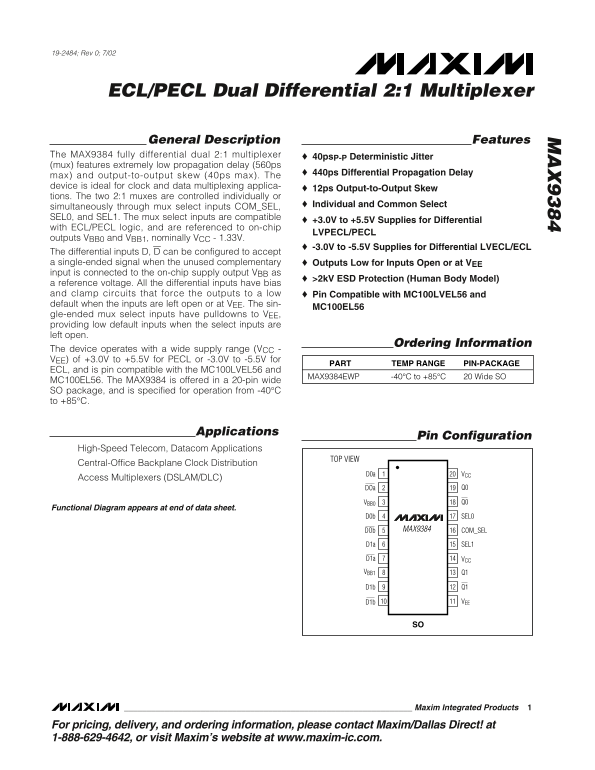
Page 1 Text Content
19-2484; Rev 0; 7/02
ECL/PECL Dual Differential 2:1 Multiplexer
General Description Features
The MAX9384 fully differential dual 2:1 multiplexer 40ps P-P Deterministic Jitter (mux) features extremely low propagation delay (560ps
440ps Differential Propagation Delay
max) and output-to-output skew (40ps max). The device is ideal for clock and data multiplexing applica-
12ps Output-to-Output Skew
tions. The two 2:1 muxes are controlled individually or
Individual and Common Select
simultaneously through mux select inputs COM_SEL, SEL0, and SEL1. The mux select inputs are compatible
+3.0V to +5.5V Supplies for Differential
with ECL/PECL logic, and are referenced to on-chip
LVPECL/PECL
outputs VBB0 and VBB1, nominally VCC - 1.33V.
-3.0V to -5.5V Supplies for Differential LVECL/ECL
The differential inputs D, D can be configured to accept a single-ended signal when the unused complementary Outputs Low for Inputs Open or at VEE
input is connected to the on-chip supply output VBB as
>2k V ESD Protection (Human Body Model)
a reference voltage. All the differential inputs have bias and clamp circuits that force the outputs to a low Pin Compatible with MC100LVEL56 and default when the inputs are left open or at VEE. The sin-
MC100EL56
gle-ended mux select inputs have pulldowns to VEE, providing low default inputs when the select inputs are left open.
Ordering Information
The device operates with a wide supply range (VCC VEE) of +3.0V to +5.5V for PECL or -3.0V to -5.5V for
PART TEMP RANGE PIN-PACKAGE
ECL, and is pin compatible with the MC100LVEL56 and
MAX9384EWP -40°C to +85°C 20 Wide SO
MC100EL56. The MAX9384 is offered in a 20-pin wide SO package, and is specified for operation from -40°C to +85°C.
Applications
Pin Configuration
High-Speed Telecom, Datacom Applications
TOP VIEW
Central-Office Backplane Clock Distribution
D0a VCC
Access Multiplexers (DSLAM/DLC)
DOa Q0
VBB0 Q0
Functional Diagram appears at end of data sheet.
SEL0D0b
DOb MAX9384 COM_SEL
D1a SEL1
D1a VCC VBB1 Q1
D1b VEE
Maxim Integrated Products
For pricing, delivery, and ordering information, please contact Maxim/Dallas Direct! at 1-888-629-4642, or visit Maxim’s website at www.maxim-ic.com.
Page Summary Contents For MAXIM MAX9384 ECL/PECL Dual Differential 2-1 Multiplexer Data Sheet/Manual
Manual Details
| Brand | Dual |
|---|---|
| Pages | 10 |
| File Size | 235.91 KB |
| Published | May 30, 2026 |
Enter the captcha to get the download link:

Frequently Asked Questions
What are the device's nominal differential jitter specifications?
The MAX9384 features extremely low propagation delay and an output-to-output skew of 40ps max.
What external voltage ranges can be supplied for operation?
It operates with a wide supply range of +3.0V to +5.5V for PECL or -3.0V to -5.5V for ECL.
How should I minimize signal skew and common-mode noise?
Reduce signal skew by matching the electrical length of the differential traces, and bypass each V CC/EE output with capacitors.
What is the required capacitor configuration for proper power filtering?
You must use high-frequency surface-mount ceramic 0.1µF and 0.01µF capacitors on every V CC/EE supply line.