LINEAR Versatile TFT LCD Bias Supply and White LED Driver in a 4mm × 4mm QFN - Design Note 440 Eddy Wells Owner's Manual
Summary
Simplify complex power design for portable electronics with this integrated TFT LCD bias supply and White LED driver. This compact solution centralizes the volatile power requirements of medium-sized color displays and high-brightness LEDs into a single 4mm x 4mm QFN package. Ideal for designers of consumer, medical, and industrial devices, it simplifies component stocking by providing fully programmable outputs that manage sequencing, dimming capabilities, and efficiency across varying power sources like Li-Ion batteries.
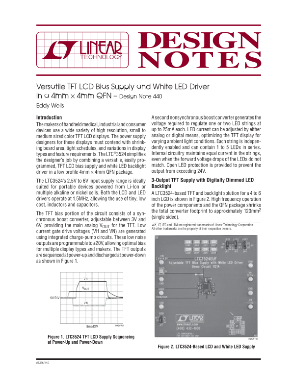
Page 1 Text Content
Versatile TFT LCD Bias Supply and White LED Driver in a 4mm × 4mm QFN – Design Note 440 Eddy Wells Introduction A second nonsynchronous boost converter generates the
The makers of handheld medical, industrial and consumer voltage required to regulate one or two LED strings at devices use a wide variety of high resolution, small to up to 25m A each. LED current can be adjusted by either medium sized color TFT LCD displays. The power supply analog or digital means, optimizing the TFT display for designers for these displays must contend with shrink- varying ambient light conditions. Each string is indepen- ing board area, tight schedules, and variations in display dently enabled and can contain 1 to 5 LEDs in series. types and feature requirements. The LTC®3524 simplifi es Internal circuitry maintains equal current in the strings, the designer’s job by combining a versatile, easily pro- even when the forward voltage drops of the LEDs do not grammed, TFT LCD bias supply and white LED backlight match. Open LED protection is provided to prevent the driver in a low profi le 4mm × 4mm QFN package. output from exceeding 24V. The LTC3524’s 2.5V to 6V input supply range is ideally 3-Output TFT Supply with Digitally Dimmed LED suited for portable devices powered from Li-Ion or Backlight
multiple alkaline or nickel cells. Both the LCD and LED A LTC3524-based TFT and backlight solution for a 4 to 6 drivers operate at 1.5MHz, allowing the use of tiny, low inch LCD is shown in Figure 2. High frequency operation cost, inductors and capacitors. of the power components and the QFN package shrinks
the total converter footprint to approximately 120mm2
The TFT bias portion of the circuit consists of a syn-
(single sided).
chronous boost converter, adjustable between 3V and
6V, providing the main analog VOUT for the TFT. Low L, LT, LTC and LTM are registered trademarks of Linear Technology Corporation. All other trademarks are the property of their respective owners.
current gate drive voltages (VH and VN) are generated using integrated charge-pump circuits. These low noise outputs are programmable to ±20V, allowing optimal bias for multiple display types and makers. The TFT outputs are sequenced at power-up and discharged at power-down as shown in Figure 1.
5V/DIV
DN4EW F01
5ms/DIV
Figure 1. LTC3524 TFT LCD Supply Sequencing
DN4EW F02
at Power-Up and Power-Down
Figure 2. LTC3524-Based LCD and White LED Supply
Page Summary Contents For LINEAR Versatile TFT LCD Bias Supply and White LED Driver in a 4mm × 4mm QFN - Design Note 440 Eddy Wells Owner's Manual
Manual Details
| Brand | Linear |
|---|---|
| Pages | 2 |
| File Size | 144.01 KB |
| Published | June 20, 2026 |
Enter the captcha to get the download link:

Frequently Asked Questions
What input voltage range can the LTC3524 accommodate?
The device handles a 2.5V to 6V input supply range, ideal for Li-Ion or nickel/alkaline cells.
How are the required display voltages sequenced at power-up?
Outputs are sequenced at power-up and actively discharged when ELCD is brought low, as shown in Figure 1.
What methods are available for dimming the LEDs?
Both analog dimming (by adjusting PROG) and PWM dimming can be implemented for varied control.