LINEAR LT3743 User Guide
Summary
This manual provides an in-depth look at the LT3743, a high-speed, regulated LED driver designed for demanding lighting applications like DLP projectors. It revolutionizes dimming by combining analog control with advanced PWM capabilities using a unique switched capacitor topology. This device ensures ultrafast, highly accurate current regulation across wide dynamic ranges, enabling precise color mixing (RGB) and maintaining high efficiency even at low duty cycles. Ideal for engineers designing professional video projection or sophisticated accent lighting systems requiring reliable performance and minimal visible flicker.
Page 1 Text Content
L DESIGN FEATURES
High Current/High Speed LED Driver Revolutionizes PWM Dimming
by Josh Caldwell Introduction
Power drivers that can produce regu- lated high current pulses are used VIN VIN
in a number of lighting applications, LT3743 HG
ranging from high current LEDs in
DLP projectors to high power laser CBOOT IREG
LED LOAD
diodes. For instance, in high end SW
video projectors, high power LEDs are
VCC_INT
used to produce color illumination.
The RGB LEDs in these projectors
LG VOUT FOR IREG VOUT FOR IREG require precise dimming control for DETERMINED DETERMINED
CTRL_SEL GND
BY CTRL_H BY CTRL_L
accurate color mixing—in this case,
SENSE+
more control than simple PWM dim- SENSE ming can offer. Typically, to achieve PWMGH
CTRL_L
the wide dynamic range required in color mixing, LED drivers must be CTRL_H PWMGL able to rapidly switch between the two disparate regulated peak current
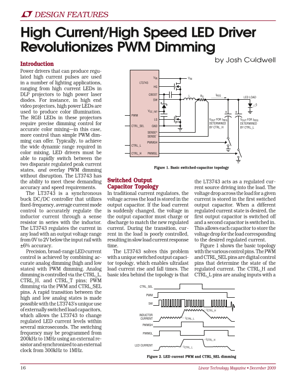
Figure 1. Basic switched-capacitor topology
states, and overlay PWM dimming without disruption. The LT3743 has
the ability to meet these demanding Switched Output the LT3743 acts as a regulated cur- accuracy and speed requirements. Capacitor Topology rent source driving into the load. The
The LT3743 is a synchronous In traditional current regulators, the voltage drop across the load for a given buck DC/DC controller that utilizes voltage across the load is stored in the current is stored in the first switched fixed-frequency, average current mode output capacitor. If the load current output capacitor. When a different control to accurately regulate the is suddenly changed, the voltage in regulated current state is desired, the inductor current through a sense the output capacitor must charge or first output capacitor is switched off resistor in series with the inductor. discharge to match the new regulated and a second capacitor is switched in. The LT3743 regulates the current in current. During the transition, cur- This allows each capacitor to store the any load with an output voltage range rent in the load is poorly controlled, voltage drop for the load corresponding from 0V to 2V below the input rail with resulting in slow load current response to the desired regulated current. ±6% accuracy. time. Figure 1 shows the basic topology Precision, broad-range LED current The LT3743 solves this problem with the various control pins. The PWM control is achieved by combining ac- with a unique switched output capaci- and CTRL_SEL pins are digital control curate analog dimming (high and low tor topology, which enables ultrafast pins that determine the state of the states) with PWM dimming. Analog load current rise and fall times. The regulated current. The CTRL_H and dimming is controlled via the CTRL_L, basic idea behind the topology is that CTRL_L pins are analog inputs with a CTRL_H, and CTRL_T pins; PWM
dimming via the PWM and CTRL_SEL CTRL_SEL
pins. A rapid transition between the
high and low analog states is made
possible with the LT3743’s unique use SW
of externally switched load capacitors, ICTRL_H
which allows the LT3743 to change INDUCTOR
CURRENT ICTRL_L
regulated LED current levels within
PWMGH
several microseconds. The switching
frequency may be programmed from PWMGL
200k Hz to 1MHz using an external re- ICTRL_H
sistor and synchronized to an external LED CURRENT
ICTRL_L
clock from 300k Hz to 1MHz.
Figure 2. LED current PWM and CTRL_SEL dimming
Linear Technology Magazine • December 2009
Page Summary Contents For LINEAR LT3743 User Guide
Manual Details
| Brand | Linear |
|---|---|
| Pages | 4 |
| File Size | 510.17 KB |
| Published | June 21, 2026 |
Enter the captcha to get the download link:

Frequently Asked Questions
What is the primary benefit of the LT3743’s switched capacitor topology?
It allows for ultrafast transition between high and low current states, capable of regulating precise LED current during rapid dimming changes.
How does the LT3743 achieve PWM dimming alongside analog control?
It combines standard PWM methods with a switched output capacitor topology that determines controllable regulated LED levels using CTRL_L and CTRL_H pins.
Does the LT3743 support external clock synchronization for dimming?
Yes, it can synchronize to an external clock (e.g., 300kHz to 1MHz) on the SYNC pin, ensuring PWM dimming edges are preserved.
What protective features are included with this LED driver?
It includes Overvoltage Protection and Voltage Output Protection to safeguard expensive equipment like high-end DLP projectors.