LINEAR Dual μModule DC-DC Regulator Achieves High Efficiency, Producing 4A Outputs from a 4.5V to 26.5V Input Range Design Note 474 by Alan Chern Owner's Manual, Specification Sheet
Summary
Streamline your PCB design with the LTM4619 µModule Regulator, a high-efficiency system-in-a-package solution. This device delivers two independently adjustable DC/DC outputs (0.8V–5V, 4A each) from a wide input voltage range of 4.5V to 26.5V. It is essential for system designers building complex boards with FPGAs and ASICs that require multiple dense power rails while minimizing component count and board space. The accompanying manual provides comprehensive details on its exceptional thermal management, efficiency across varying loads, и optimal multi-phase operation guidelines.
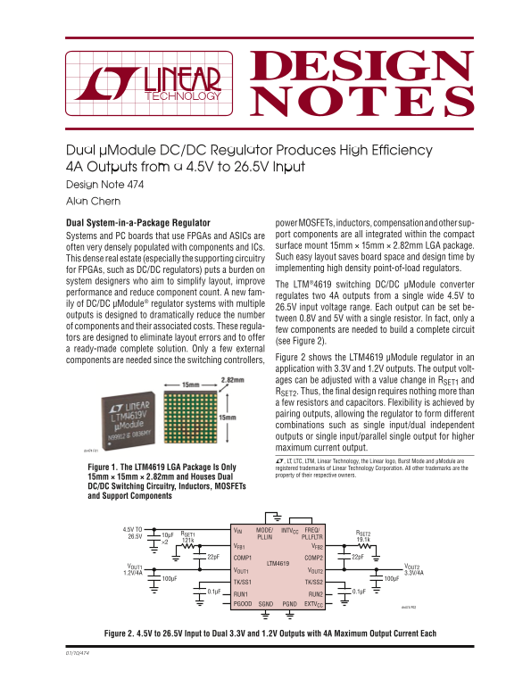
Page 1 Text Content
Dual µModule DC/DC Regulator Produces High Effi ciency 4A Outputs from a 4.5V to 26.5V Input Design Note 474 Alan Chern Dual System-in-a-Package Regulator power MOSFETs, inductors, compensation and other sup-
Systems and PC boards that use FPGAs and ASICs are port components are all integrated within the compact often very densely populated with components and ICs. surface mount 15mm × 15mm × 2.82mm LGA package. This dense real estate (especially the supporting circuitry Such easy layout saves board space and design time by for FPGAs, such as DC/DC regulators) puts a burden on implementing high density point-of-load regulators.
system designers who aim to simplify layout, improve
The LTM®4619 switching DC/DC μModule converter
performance and reduce component count. A new fam-
regulates two 4A outputs from a single wide 4.5V to
ily of DC/DC μModule® regulator systems with multiple
26.5V input voltage range. Each output can be set be-
outputs is designed to dramatically reduce the number
tween 0.8V and 5V with a single resistor. In fact, only a
of components and their associated costs. These regula-
few components are needed to build a complete circuit
tors are designed to eliminate layout errors and to offer
(see Figure 2).
a ready-made complete solution. Only a few external
Figure 2 shows the LTM4619 μModule regulator in an
components are needed since the switching controllers,
application with 3.3V and 1.2V outputs. The output volt- ages can be adjusted with a value change in RSET1 and RSET2. Thus, the fi nal design requires nothing more than a few resistors and capacitors. Flexibility is achieved by pairing outputs, allowing the regulator to form different combinations such as single input/dual independent outputs or single input/parallel single output for higher dn474 F01 maximum current output. L, LT, LTC, LTM, Linear Technology, the Linear logo, Burst Mode and μModule are
Figure 1. The LTM4619 LGA Package Is Only registered trademarks of Linear Technology Corporation. All other trademarks are the
property of their respective owners.
15mm × 15mm × 2.82mm and Houses Dual DC/DC Switching Circuitry, Inductors, MOSFETs and Support Components
4.5V TO VIN INTVCCMODE/ FREQ/
RSET1 RSET2
PLLIN PLLFLTR
VFB1 VFB2
22p F COMP1 COMP2 22p F
LTM4619
VOUT1 VOUT2
VOUT1 VOUT2
TK/SS1 TK/SS2
RUN1 RUN2 PGOOD SGND PGND EXTVCC
dn474 F02
Figure 2. 4.5V to 26.5V Input to Dual 3.3V and 1.2V Outputs with 4A Maximum Output Current Each
Page Summary Contents For LINEAR Dual μModule DC-DC Regulator Achieves High Efficiency, Producing 4A Outputs from a 4.5V to 26.5V Input Range Design Note 474 by Alan Chern Owner's Manual, Specification Sheet
Manual Details
| Brand | Linear |
|---|---|
| Pages | 2 |
| File Size | 210.09 KB |
| Published | June 21, 2026 |
Enter the captcha to get the download link:

Frequently Asked Questions
What is the supported input voltage range?
The regulator accepts a wide input voltage range from 4.5V to 26.5V.
How can I adjust the outputs for different voltages?
The output voltages are adjustable using external resistors R SET1 and R SET2, allowing settings between 0.8V and 5V.
What is the maximum current capability when running dual outputs in parallel?
This setup allows single input/parallel single output operation to achieve higher overall maximum current.
If I need additional cooling for multiple rails, what mechanism should I use?
For four-phase systems requiring added cooling, use a heat sink on top of the part or utilize a metal chassis.