Intersil ICL7112 12-Bit High-Speed CMOS µP-Compatible ADC Data Sheet
Summary
This comprehensive manual details the ICL7112, a high-speed, 12-bit successive approximation Analog-to-Digital Converter (ADC). Ideal for professionals designing data acquisition systems requiring exceptional linearity and accuracy with low power consumption. The guide provides detailed electrical specifications, pinouts, operating conditions across various temperatures, and practical application examples—including microcontroller interfacing and array scaling—enabling seamless integration into complex measurement and processing equipment.
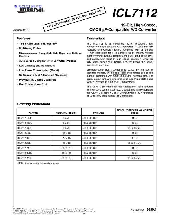
Page 1 Text Content
查询ICL7112供应商
ICL7112 12-Bit, High-Speed,
NOT RECOMMENDED FOR NEW DESIGNS
January 1998 CMOS µP-Compatible A/D Converter
Features Description 12-Bit Resolution and Accuracy The ICL7112 is a monolithic 12-bit resolution, fast
successive approximation A/D converter. It uses thin film
No Missing Codes
resistors and CMOS circuitry combined with an on-chip Microprocessor Compatible Byte-Organized Buffered PROM calibration table to achieve 12-bit linearity without Outputs laser trimming. Special design techniques used in the DAC and comparator result in high speed operation, while the
Auto-Zeroed Comparator for Low Offset Voltage
fully static silicon-gate CMOS circuitry keeps the power dissipation very low.
Low Linearity and Gain Errors
Microprocessor bus interfacing is eased by the use of
Low Power Consumption (60m W)
standard memory WRite and Rea D cycle timing and control
No Gain or Offset Adjustment Necessary
signals, combined with Chip Select and Address pins. The digital output pins are byte-organized and three-state gated
Provides 3% Usable Overrange
for bus interface to 8-bit and 16-bit systems.
Fast Conversion (40µs)
The l CL7112 provides separate Analog and Digital grounds for increased system accuracy. Operating with ±5V supplies, the l CL7112 accepts 0V to +10V input with a -10V reference or 0V to -10V input with a +10V reference.
Ordering Information
RESOLUTION WITH NO MISSION
PART NO. TEMP. RANGE (o C) PACKAGE CODES
ICL7112JCDL 0 to 70 40 Ld CERDIP 11-Bit
ICL7112KCDL 0 to 70 40 Ld CERDIP 12-Bit
ICL7112LCDL 0 to 70 40 Ld CERDIP 12-Bit (Note)±
ICL7112JIDL -25 to 85 40 Ld CERDIP 11-Bit
ICL7112KIDL -25 to 85 40 Ld CERDIP 12-Bit
ICL7112LIDL -25 to 85 40 Ld CERDIP 12-Bit (Note)±
ICL7112JMDL -55 to 125 40 Ld CERDIP 11-Bit
ICL7112KMDL -55 to 125 40 Ld CERDIP 12-Bit
ICL7112LMDL -55 to 125 40 Ld CERDIP 12-Bit (Note)±
NOTE: Over operating temperature range.
CAUTION: These devices are sensitive to electrostatic discharge; follow proper IC Handling Procedures.
File Number 3639.1
1-888-INTERSIL or 321-724-7143 Intersil (and design) is a registered trademark of Intersil Americas Inc. Copyright © Intersil Americas Inc. 2002. All Rights Reserved
Page Summary Contents For Intersil ICL7112 12-Bit High-Speed CMOS µP-Compatible ADC Data Sheet
Manual Details
| Brand | ADC |
|---|---|
| Pages | 14 |
| File Size | 592.42 KB |
| Published | May 13, 2026 |
Enter the captcha to get the download link:

Frequently Asked Questions
What is the resolution and speed of the ICL7112?
It provides a 12-bit resolution and has a fast conversion rate of 40µs.
How far can the input voltage range extend?
When operating with ±5V supplies, it accepts inputs from 0V to +10V or 0V to -10V.
Is professional calibration required for high accuracy?
No, specialized design techniques allow for 12-bit linearity without needing laser trimming.
What are the operating temperature options available?
Temperature ranges include commercial (0 to 70°C), industrial (-40 to 85°C), and military grade (-55 to 125°C).