Page 1
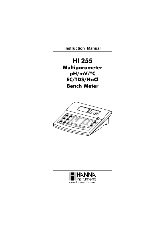
Instruction Manual HI 255 Multiparameter p H/m V/ºC EC/TDS/Na Cl Bench Meter www.hannains com
Page 2
Dear Customer, Thank you for choosing a Hanna Instruments product. Please read this instruction manual carefully before using the instrument. This manual will provide you with the necessary informatio...
Page 3
PRELIMINARY EXAMINATION Remove the instrument from the packing material and examine it carefully to make sure that no damage has occurred during shipping. If there is any damage, notify your Dealer or...
Page 4
FUNCTIONAL DESCRIPTION Primary LCD Front Panel Secondary LCD p Hm Vg / l LOGCAL INTVDATETIME% Na Cl BUFFER p H READY ppm BUFWRONG ALT Functions Functions RANGE Select Measure Unit Select Measure Mode ...
Page 5
HI 255 SPECIFICATIONS Hp00.61ot00.2 Hp000.61ot000.2 Vm9.996± Vm0002± 99.92ot00.0 mc/S 9.992ot0.03 mc/S 9992ot003 mc/S mc/Sm99.92ot00.3 mc/Sm0.002ot0.03 lautcamc/Sm0.005otpu ytivitcudnoc EGNAR mpp99....
Page 6
HI 255 SPECIFICATIONS (cont.) egnartesffo Vmle R Vm0002± ecafretniretupmo C 232SRdetalosi-otpo ;noitarbilactniop3ro2,1 noitarbila CHp elbaliavasreffub5 )10.01,81.9,10.7,68.6,10.4( ;noitarbilacepolstni...
Page 7
OPERATIONAL GUIDE POWER CONNECTION Plug the 12 VDC adapter into the power supply socket. Note: This instrument uses non volatile memory to retain the calibration parameters and all other settings, eve...
Page 8
The p H is displayed on the primary LCD and the temperature on the secondary LCD. If the reading is out of range, the closest full-scale value will be displayed blinking on the primary LCD. If measure...
Page 9
The instrument displays the m V reading on the primary LCD and the temperature on the secondary LCD line. If the reading is out of range, the closest full-scale value will be displayed blinking on the...
Page 10
If LOCK was pressed to freeze the LCD range and the reading went out of range, the full-scale value of the frozen range will be displayed blinking. The EC reading is affected by temperature. Three opt...
Page 11
If the reading is out of range, the full-scale value (100.0 for Mtc/Atc mode or 400.0 for actual TDS) will be displayed blinking. If LOCK was pressed to freeze the LCD range and the reading went out o...
Page 12
p H CALIBRATION Calibrate the instrument frequently, especially if high accuracy is required. The instrument should be recalibrated : Whenever the p H electrode is replaced. At least once a week. Afte...
Page 13
The tag will blink on the LCD until the reading is stable. When the reading is stable and close to the selected buffer, READY tag will be displayed and CFM tag will blink. Press CFM to confirm...
Page 14
Note: If the value measured by the instrument is not close to the selected buffer, WRONG BUF and WRONG tags will blink alternately. In this case, check if the correct buffer has been used or...
Page 15
RELATIVE m V CALIBRATION Press CAL when the instrument is in RELATIVE m V measurement mode. The m V and tags will blink. Absolute m V is displayed on the primary LCD and Ab S message is displa...
Page 16
EC/TDS CALIBRATION EC calibration is a one-point procedure. Selectable calibration points are 0.00 µS for offset and 84.0 µS, 1413 µS, 5.00 m S, 12.88 m S, 80.0 m S, 111.8 m S for slope. Rinse the pro...
Page 17
If the meter is in Atc mode and the buffer temperature is out of 0.0 60.0 ºC interval, WRONG ºC tags and the temperature will be displayed blinking. CAL WRONG For best results choose an EC buffe...
Page 18
Na Cl CALIBRATION Na Cl calibration is a one-point procedure at 100.0% Na Cl. Use the HI 7037L calibration solution (sea water solution) as a 100% Na Cl standard solution. Rinse the probe with some of...
Page 19
GOOD LABORATORY PRACTICE (GLP) GLP is a set of functions that allows storage and retrieval of data regarding the maintenance and status of the electrode. All data regarding p H, Rel m V, EC and Na Cl ...
Page 20
The p H calibration slope(the GLP slope is the average of the calibration slopes; the percentage is referred to the ideal value of 59.16 m V/p H). The calibration buffers in calibrating order. The fir...
Page 21
Calibration Alarm Time-Out status: if disabled. or the number of days until the calibration alarm will be displayed. or if expired (7 days ago). INTVCAL The instrument ID. LAST Relative m V CALIBRAT...
Page 22
The Relative m V calibration offset: The instrument ID. LAST EC CALIBRATION DATA Last EC calibration data is stored automatically after a successful calibration. To view the EC calibration data, pre...
Page 23
The reference temperature. The temperature coefficient. The temperature compensation mode. The instrument ID. LAST Na Cl CALIBRATION DATA Last Na Cl calibration data is stored automatically after a su...
Page 24
The cell constant. The reference temperature. The temperature compensation mode. The instrument ID. Note: If notc is selected as temperature compensation mode during calibration, the temperature coeff...
Page 25
LOGGING FUNCTION Up to 200 LOG samples can be stored into memory. LOGGING THE CURRENT DATA To store the current reading into memory press LOG while the instrument is in measurement mode. The instrumen...
Page 26
On Relative m V range: LOG m V On EC range: On TDS range: LOG On Na Cl range: Otherwise, the instrument will display the memorized data: If RCL is invoked while the instrument is in p H or m V measure...
Page 27
Or if RCL is invoked while the instrument is in Na Cl measurement range: Pressing the ARROW keys, the instrument will display the same parameter but for a different record: (example on p H range) p HL...
Page 28
The time on the primary LCD, along with TIME tag. TIMELOG The date on the primary LCD, along with DATE tag. DATELOG The calibration offset on the primary LCD and OFS message on the secondary LCD...
Page 29
Pressing the ALT&SET keys again, the secondary LCD will display the record number. Press CFM to confirm deletion. If d EL ALL option was selected, all records (for all ranges) are deleted and th...
Page 30
When the information that does not display the record number is selected, pressing and keeping hold down the ALT&SET keys will display the record number on the secondary LCD line. The d EL messa...
Page 31
SETUP Setup mode allows viewing and modifying the instrument parameters. In according with the selected range, SETUP menu allows the possibility to view and/or change specific range parameters and com...
Page 32
SET COMMON PARAMETERS Instrument ID parameter Press CAL when the instrument ID is displayed. The instrument ID (0000 to 9999) will start blinking. Press the ARROW keys to change the instrument ID valu...
Page 33
Press RANGE. The month will start blinking. Press the ARROW keys to change the month. Press RANGE. The day will start blinking. Press the ARROW keys to change the day. Press CFM to save the modified v...
Page 34
Serial Communication Command Prefix Set Press CAL when the command prefix is displayed. Command prefix (0 to 47) will start blinking. Press the ARROW keys to change the command prefix. Press CFM to sa...
Page 35
TDS Factor Set Press CAL when the TDS factor is displayed. The TDS factor will start blinking. Press the ARROW keys to change the TDS factor (0.40 to 0.80). Press CFM to save the modified TDS factor. ...
Page 36
TEMPERATURE CALIBRATION( for technica personnel only The instrument has two temperature channels: one that measures the tem- perature from the HI 7662 probe while the instrument is in p H/m V range an...
Page 37
Immerse the temperature probe (or EC probe) in the second vessel as near as possible to the calibrated thermometer. Allow a few seconds for the probe to stabilize. Use the ARROW keys to set the readin...
Page 38
m V CALIBRATION for technica personnel only All the instruments are factory calibrated for m V. Hannas ORP electrodes are interchangeable and no m V calibration is needed when they are replaced. If t...
Page 39
PC INTERFACE Data transmission from the instrument to the PC can be done with the HI 92000 Windows® compatible software (optional). HI 92000 also offers graphing and on-line help feature. Data can be ...
Page 40
n=1 p H range/0.1 resolution n=2 m V range n=3 Relative m V range n=4 EC range n=5 TDS range n=6 Na Cl range The instrument sends the ACK (6) character every time a command is recognized and a NAK...