FAIRCHILD TL494 SMPS Controller Data Sheet User Manual
Summary
The TL494 is a specialized Semiconductor Integrated Circuit designed as a highly versatile Smart Power Supply (SMPS) controller for PWM-trimmed switching regulators. This device provides stable voltage reference, advanced dead time control, and robust output management for both push-pull and single-ended applications. The comprehensive manual provides engineers with detailed electrical specifications, operational parameters, and design guidelines needed to accurately build reliable and efficient switched power conversion circuits. Essential for hardware designers developing professional-grade power supplies.
Page 1 Text Content
www.fairchildsemi.com
TL494 SMPS Controller
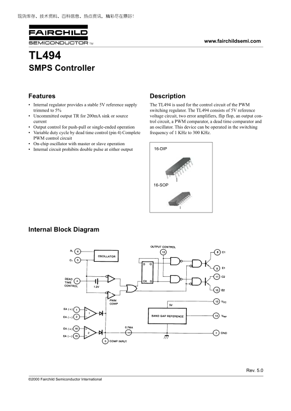
Features Description Internal regulator provides a stable 5V reference supply The TL494 is used for the control circuit of the PWM trimmed to 5% switching regulator. The TL494 consists of 5V reference Uncommitted output TR for 200m A sink or source voltage circuit, two error amplifiers, flip flop, an output con- current trol circuit, a PWM comparator, a dead time comparator and Output control for push-pull or single-ended operation an oscillator. This device can be operated in the switching Variable duty cycle by dead time control (pin 4) Complete frequency of 1 KHz to 300 KHz. PWM control circuit On-chip oscillator with master or slave operation
Internal circuit prohibits double pulse at either output 16-DIP
16-SOP
Internal Block Diagram
Rev. 5.0
©2000 Fairchild Semiconductor International
Page Summary Contents For FAIRCHILD TL494 SMPS Controller Data Sheet User Manual
Manual Details
| Brand | Fairchild |
|---|---|
| Pages | 8 |
| File Size | 72.40 KB |
| Published | May 19, 2026 |
Enter the captcha to get the download link:

Frequently Asked Questions
What is the primary function of the TL494?
The TL494 controls the circuit for a PWM trimmed switching regulator and provides a stable 5V reference supply.
What are the supported operating temperatures and package codes?
Options include TL494CN (0 ~ +70°C) or options sold with STG which support -65 ~ +150°C.
How can I adjust the switching cycle?
The device allows for variable duty cycle control using dead time control via pin 4, limiting the maximum duty cycle to 45%.
What is the minimum/maximum operating frequency range?
The on-chip oscillator supports a complete frequency range from 1 KHz up to 300 KHz.