FAIRCHILD SG6742 - High-Performance Integrated Green-Mode PWM Controller Data Sheet User Manual
Summary
This highly integrated PWM controller series offers a comprehensive solution for designing high-efficiency, compact flyback converters and general switch-mode power supplies. The accompanying manual provides detailed design strategies, PCB layout guidelines, and mathematical considerations, focusing on meeting modern international power conservation standards through proprietary green-mode functionality and ultra-low standby current draw (2.7mA). Ideal for engineers developing open-frame SMPS and power adapters requiring robust protection features (UVLO, OVP) and reliable performance across a wide AC input voltage range.
Page 1 Text Content
www.fairchildsemi.com
AN-6077 SG6742 — Highly Integrated Green-Mode PWM Controller
Abstract Introduction
The highly integrated SG6742 series of PWM controllers
This application note describes a detailed design strategy for
provides several features to enhance the performance of
a high-efficiency, compact flyback converter. Design
flyback converters.
considerations, mathematical equations, and guidelines for a Printed-Circuit-Board (PCB) layout are presented. To minimize standby power consumption, a proprietary
green-mode function provides off-time modulation to Features linearly decrease the switching frequency at light-load conditions. To avoid acoustic-noise problems, the minimum
High-Voltage Startup PWM frequency is set above 22KHz. This green-mode
Low Operating Current: 2.7m A function enables the power supply to meet international Linearly Decreasing PWM Frequency to 22KHz power conservation requirements. With the internal high- Frequency Hopping to Reduce EMI Emission voltage startup circuitry, the power loss due to bleeding resistors is also eliminated. To further reduce power
Fixed PWM Frequency:
consumption, SG6742 is manufactured using the Bi CMOS
ML and MR are 65KHz.
process, which allows an operating current of only 2.7m A.
HL and HR are 100KHz. Peak-Current-Mode Control Built-in synchronized slope compensation achieves stable
Cycle-by-Cycle Current Limiting peak-current-mode control. The proprietary external line Leading-Edge Blanking (LEB) compensation ensures a constant output-power limit over a wide AC input voltage range, from 90VAC to 264VAC.
Synchronized Slope Compensation Internal Open-Loop Protection SG6742 provides many protection functions. In addition to Gate Output Maximum Voltage Clamp: 18V cycle-by-cycle current limiting, the internal open-loop
VDD Under-Voltage Lockout (UVLO) protection circuit ensures safety should an open-loop or VDD Over-Voltage Protection (OVP) output short-circuit failure occur.
Programmable Over-Temperature Protection (OTP)
Internal Latch Circuit (OVP, OTP) (VDD) OLP (FB) OTP (RT) (SENSE) Frequency Internal Sense Short-Circuit Protection SG6742ML Latch Latch Latch Auto Restart 65KHz
Built-In Soft-Start Function SG6742MR Latch Auto Restart Latch Auto Restart 65KHz SG6742HL Latch Latch Latch Auto Restart 100KHz
ML and MR are 5ms.
SG6742HR Latch Auto Restart Latch Auto Restart 100KHz
HL and HR are 6ms. Constant Power Limit (Full AC Input Range)
SOP-8
Internal OTP Sensor with Hysteresis
GND GATE
Applications
FB VDD
General-purpose, switch-mode power supplies and flyback power converters, including:
NC SENSE
Power Adapters
HV RT
Open-Frame Switch-Mode Power Supply (SMPS)
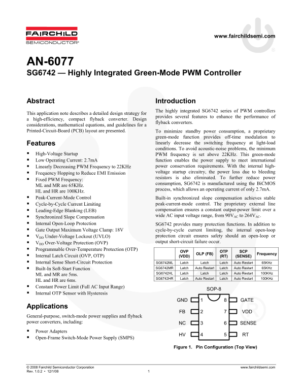
Figure 1. Pin Configuration (Top View)
© 2008 Fairchild Semiconductor Corporation www.fairchildsemi.com Rev. 1.0.2 • 12/1/08 1
Page Summary Contents For FAIRCHILD SG6742 - High-Performance Integrated Green-Mode PWM Controller Data Sheet User Manual
Manual Details
| Brand | Fairchild |
|---|---|
| Pages | 8 |
| File Size | 319.36 KB |
| Published | May 19, 2026 |
Enter the captcha to get the download link:

Frequently Asked Questions
How does this controller reduce standby power consumption?
It uses a proprietary green-mode function with off-time modulation to decrease switching frequency at light loads, allowing for an operating current of only 2.7mA.
What protections are built into the SG6742 chip?
The controller features internal open-loop protection, Over-Voltage Protection (OVP), Under-Voltage Lockout (UVLO), and Programmable Over-Temperature Protection (OTP).
Are there specific layout requirements for PCB design?
Yes, the area enclosed by the transformer auxiliary winding and associated traces should be at least 5mm. The decoupling capacitor (C) should be placed close to the SG6742.
What AC input voltage range can this device operate within?
It provides continuous operation across a wide AC input voltage range, from 90V to 264V.