Fairchild QTLP610CIR Infrared Emitting Diode Surface Mount Right Angle Data Manual
Summary
This comprehensive manual is designed for electrical engineers and hardware designers utilizing infrared technology. It details the QTLP610CIR, a right angle surface mount IR emitting diode with a 940 nm wavelength. The document provides critical technical resources including electrical and optical performance curves, detailed absolute maximum ratings, physical dimensions, recommended PCB patterns, and precise reflow soldering procedures. Use this resource to ensure reliable integration of advanced infrared communication into your electronic products.
Page 1 Text Content
RIGHT ANGLE SURFACE MOUNT INFRARED EMITTING DIODE
QTLP610CIR
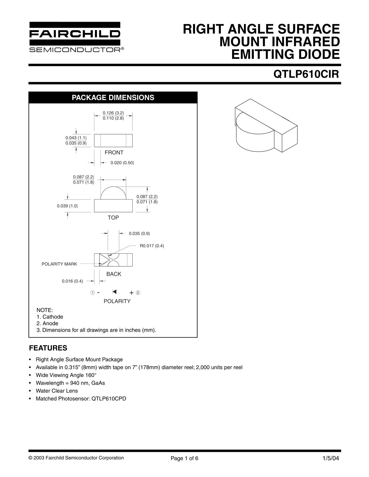
PACKAGE DIMENSIONS
POLARITY MARK
POLARITY
NOTE: 1. Cathode 2. Anode 3. Dimensions for all drawings are in inches (mm).
FEATURES Right Angle Surface Mount Package Available in 0.315” (8mm) width tape on 7” (178mm) diameter reel; 2,000 units per reel Wide Viewing Angle 160° Wavelength = 940 nm, Ga As Water Clear Lens Matched Photosensor: QTLP610CPD
© 2003 Fairchild Semiconductor Corporation Page 1 of 6 1/5/04
Page Summary Contents For Fairchild QTLP610CIR Infrared Emitting Diode Surface Mount Right Angle Data Manual
Manual Details
| Brand | Fairchild |
|---|---|
| Pages | 6 |
| File Size | 191.94 KB |
| Published | July 07, 2026 |
Enter the captcha to get the download link:

Frequently Asked Questions
What are the recommended soldering procedures for installation?
Use an IR reflow soldering profile with a maximum time of 240°C and maximum ramps of +/-5°C/s. RMA flux is also recommended.
What is the specified operational temperature range?
The operating temperature (T) range is -40 to +85°C, while storage can handle -40 to +90°C.
How is polarity determined on the component?
Polarity requires identifying Pin 1 as Cathode and Pin 2 or 3 as Anode.
Could this diode be used in critical life support systems?
No, Fairchild's products are not authorized for use as critical components in life support devices without express written approval.