Fairchild MMBT4354 PNP General Purpose Amplifier Data Sheet
Summary
The MMBT4354 is a reliable PNP General Purpose Amplifier transistor designed for switching applications requiring up to 500mA collector current. This professional datasheet provides comprehensive technical details necessary for circuit design, covering absolute maximum ratings, key electrical characteristics (like gain and saturation voltage), thermal management guidelines, and precise physical dimensions in an SOT-23 package. It is ideal for electronics engineers and designers building reliable amplification or switching circuits into their embedded systems.
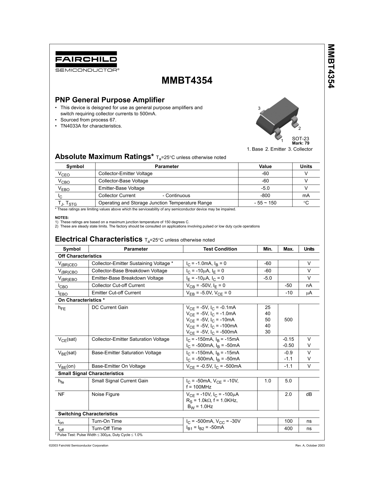
Page 1 Text Content
MMBT4354
PNP General Purpose Amplifier This device is deisgned for use as general purpose amplifiers and switch requiring collector currents to 500m A. Sourced from process 67. TN4033A for characteristics.
SOT-23 Mark: 79
1. Base 2. Emitter 3. Collector
Absolute Maximum Ratings* Ta=25°C unless otherwise noted Symbol Parameter Value Units
VCEO Collector-Emitter Voltage -60 VCBO Collector-Base Voltage -60 VEBO Emitter-Base Voltage -5.0
IC Collector Current - Continuous -800 m A
TJ, TSTG Operating and Storage Junction Temperature Range - 55 ~ 150 °C
* These ratings are limiting values above which the serviceability of any semiconductor device may be impaired.
NOTES: 1) These ratings are based on a maximum junction temperature of 150 degrees C. 2) These are steady state limits. The factory should be consulted on applications involving pulsed or low duty cycle operations
Electrical Characteristics Ta=25°C unless otherwise noted Symbol Parameter Test Condition Min. Max. Units Off Characteristics
V(BR)CEO Collector-Emitter Sustaining Voltage * IC = -1.0m A, IB = 0 -60 V(BR)CBO Collector-Base Breakdown Voltage IC = -10µA, IE = 0 -60 V(BR)EBO Emitter-Base Breakdown Voltage IE = -10µA, IC = 0 -5.0 ICBO Collector Cut-off Current VCB = -50V, IE = 0 -50 n A IEBO Emitter Cut-off Current VEB = -5.0V, VCE = 0 -10 µA
On Characteristics * h FE DC Current Gain VCE = -5V, IC = -0.1m A
VCE = -5V, IC = -1.0m A VCE = -5V, IC = -10m A VCE = -5V, IC = -100m A VCE = -5V, IC = -500m A
VCE(sat) Collector-Emitter Saturation Voltage IC = -150m A, IB = -15m A -0.15
IC = -500m A, IB = -50m A -0.50
VBE(sat) Base-Emitter Saturation Voltage IC = -150m A, IB = -15m A -0.9 IC = -500m A, IB = -50m A -1.1
VBE(on) Base-Emitter On Voltage VCE = -0.5V, IC = -500m A -1.1
Small Signal Characteristics hfe Small Signal Current Gain IC = -50m A, VCE = -10V, 1.0 5.0
f = 100MHz
NF Noise Figure VCE = -10V, IC = -100µA 2.0 d B
RS = 1.0kΩ, f = 1.0KHz, BW = 1.0Hz
Switching Characteristics ton Turn-On Time IC = -500m A, VCC = -30V ns
toff Turn-Off Time IB1 = IB2 = -50m A ns
* Pulse Test: Pulse Width ≤ 300µs, Duty Cycle ≤ 1.0%
©2003 Fairchild Semiconductor Corporation Rev. A, October 2003
Page Summary Contents For Fairchild MMBT4354 PNP General Purpose Amplifier Data Sheet
Manual Details
| Brand | Fairchild |
|---|---|
| Pages | 4 |
| File Size | 47.62 KB |
| Published | July 12, 2026 |
Enter the captcha to get the download link:

Frequently Asked Questions
What is the maximum continuous collector current?
The absolute maximum continuous collector current (I_C) for this device is -800 mA.
What are the operating temperature limits for this amplifier?
The junction temperature range (Tj/Junction Temperature) for operation and storage is -55 to 150 °C.
How large can the dissipation be at room temperature?
The maximum total device dissipation before derating is 350 mW, with a thermal resistance (θJA) of 357 °C/W on an FR-4 PCB.
Does this part have restrictions for critical applications?
No, according to the Life Support Policy, Fairchild’s products are not authorized for use as critical components in life support devices without expressed written approval.