Fairchild ISL9K1560G3 15A, 600V Stealth Dual Diode Data Manual
Summary
Engineered for robust performance in high-frequency environments, this Stealth™ dual diode is a low-loss solution optimized for hard-switched applications like SMPS and PFC boosts. Featuring soft recovery and fast response times up to 600V, it ensures maximum efficiency while minimizing circuit ringing, making it ideal for universal power management units and UPS systems. This technical manual provides electrical characteristics, thermal guidelines, and performance curves necessary for professional power electronics engineers designing reliable switching circuits.
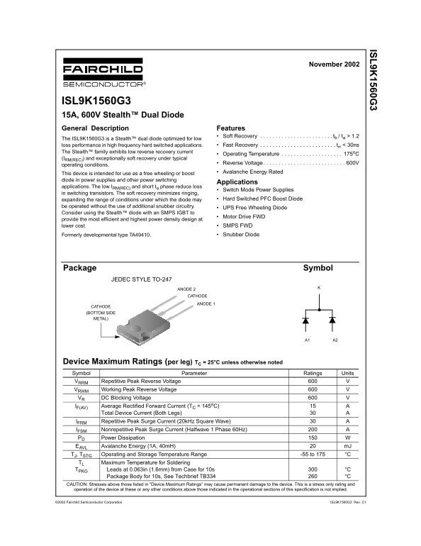
Page 1 Text Content
IS 9K 1560G
November 2002
ISL9K1560G3 15A, 600V Stealth™ Dual Diode General Description Features
Soft Recovery . . . . . . . . . . . . . . . . . . . . . . . . tb / ta > 1.2
The ISL9K1560G3 is a Stealth™ dual diode optimized for low
loss performance in high frequency hard switched applications. Fast Recovery . . . . . . . . . . . . . . . . . . . . . . . . . trr < 30ns
The Stealth™ family exhibits low reverse recovery current
Operating Temperature . . . . . . . . . . . . . . . . . . . . 175o C
(IRM(REC)) and exceptionally soft recovery under typical
Reverse Voltage . . . . . . . . . . . . . . . . . . . . . . . . . . . 600V
operating conditions.
Avalanche Energy Rated
This device is intended for use as a free wheeling or boost diode in power supplies and other power switching
Applications
applications. The low IRM(REC) and short ta phase reduce loss
Switch Mode Power Supplies
in switching transistors. The soft recovery minimizes ringing,
expanding the range of conditions under which the diode may Hard Switched PFC Boost Diode
be operated without the use of additional snubber circuitry.
UPS Free Wheeling Diode
Consider using the Stealth™ diode with an SMPS IGBT to
Motor Drive FWD
provide the most efficient and highest power density design at
lower cost. SMPS FWD Formerly developmental type TA49410. Snubber Diode
Package Symbol
JEDEC STYLE TO-247
ANODE 2 CATHODE
ANODE 1
CATHODE (BOTTOM SIDE METAL)
Device Maximum Ratings (per leg) TC = 25°C unless otherwise noted Symbol Parameter Ratings Units VRRM Repetitive Peak Reverse Voltage
VRWM Working Peak Reverse Voltage VR DC Blocking Voltage IF(AV) Average Rectified Forward Current (TC = 145o C) Total Device Current (Both Legs)
IFRM Repetitive Peak Surge Current (20k Hz Square Wave)
IFSM Nonrepetitive Peak Surge Current (Halfwave 1 Phase 60Hz)
PD Power Dissipation
EAVL Avalanche Energy (1A, 40m H) m J TJ, TSTG Operating and Storage Temperature Range -55 to 175 °C TL Maximum Temperature for Soldering
TPKG Leads at 0.063in (1.6mm) from Case for 10s °C
Package Body for 10s, See Techbrief TB334 °C
CAUTION: Stresses above those listed in “Device Maximum Ratings” may cause permanent damage to the device. This is a stress only rating and operation of the device at these or any other conditions above those indicated in the operational sections of this specification is not implied.
2002 Fairchild Semiconductor Corporation ISL9K1560G3 Rev. C1
Page Summary Contents For Fairchild ISL9K1560G3 15A, 600V Stealth Dual Diode Data Manual
Manual Details
| Brand | Fairchild |
|---|---|
| Pages | 6 |
| File Size | 146.89 KB |
| Published | May 31, 2026 |
Enter the captcha to get the download link:

Frequently Asked Questions
What is the maximum continuous forward current?
The average rectified forward current (IF(AV)) is specified at 15 A for operation at T = 145°C.
How high can the device operate in temperature extreme conditions?
The operating and storage temperature range is -55 to 175 °C.
Is this diode suitable for PFC boost applications?
Yes, it is ideal as a free wheeling or boost diode in power supplies and hard switched PFC Boost Diode applications.
What are the key performance features of the ISL9K1560G3?
It offers Soft Recovery and Fast Recovery alongside low reverse recovery current (IrRM(REC)).