# A B C D E F G H I J K L M N O P Q R S T U V W X Y Z

Fairchild Fan73832 Half-Bridge Gate-Drive IC Data Handbook

Summary

This robust half-bridge gate-drive IC is engineered for reliable power control of MOSFETs and IGBTs up to +600V. The comprehensive guide details advanced features, including programmable dead-time control, integrated UVLO protection on both channels, and common-mode dv/dt noise canceling technology for stable operation in high-noise environments. It is essential for electronics professionals designing full-bridge systems, including SMPS inverters, motor drivers, and various industrial ballasts.
📄 Preview PAGE OF 16

Page 1 Text Content

FA 73832 H alf-B ridge G ate-D rive IC

February 2007

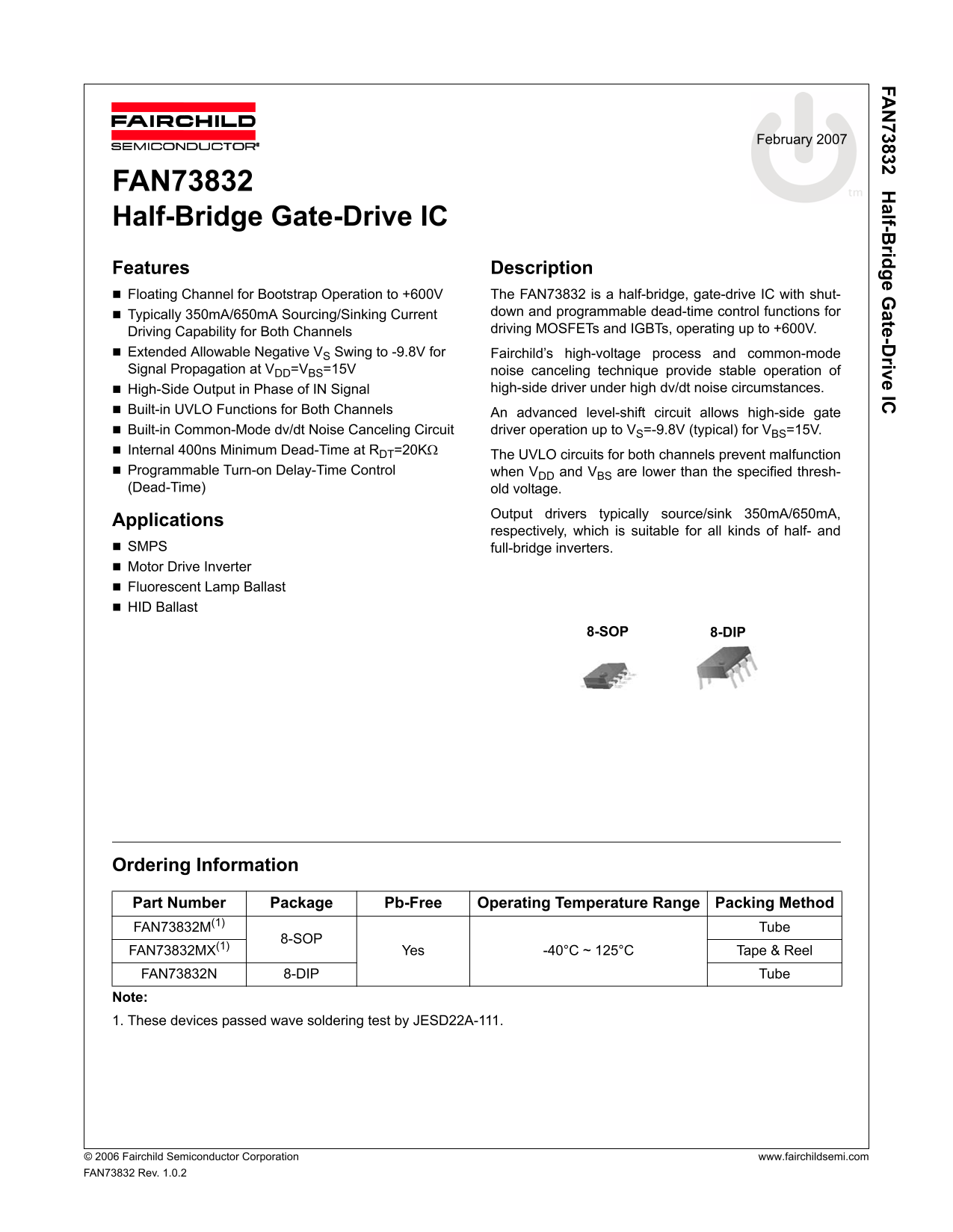
FAN73832 Half-Bridge Gate-Drive IC Features Description Floating Channel for Bootstrap Operation to +600V The FAN73832 is a half-bridge, gate-drive IC with shut-

Typically 350m A/650m A Sourcing/Sinking Current down and programmable dead-time control functions for Driving Capability for Both Channels driving MOSFETs and IGBTs, operating up to +600V.

Extended Allowable Negative VS Swing to -9.8V for Fairchild’s high-voltage process and common-mode Signal Propagation at VDD=VBS=15V noise canceling technique provide stable operation of

High-Side Output in Phase of IN Signal high-side driver under high dv/dt noise circumstances.

Built-in UVLO Functions for Both Channels An advanced level-shift circuit allows high-side gate Built-in Common-Mode dv/dt Noise Canceling Circuit driver operation up to VS=-9.8V (typical) for VBS=15V. Internal 400ns Minimum Dead-Time at RDT=20KΩ

The UVLO circuits for both channels prevent malfunction

Programmable Turn-on Delay-Time Control when VDD and VBS are lower than the specified thresh- (Dead-Time) old voltage.

Output drivers typically source/sink 350m A/650m A,

Applications

respectively, which is suitable for all kinds of half- and

SMPS full-bridge inverters. Motor Drive Inverter Fluorescent Lamp Ballast HID Ballast

8-SOP 8-DIP

Ordering Information Part Number Package Pb-Free Operating Temperature Range Packing Method

FAN73832M(1) Tube

8-SOP

FAN73832MX(1) Yes -40°C ~ 125°C Tape & Reel FAN73832N 8-DIP Tube Note: 1. These devices passed wave soldering test by JESD22A-111.

© 2006 Fairchild Semiconductor Corporation www.fairchildsemi.com FAN73832 Rev. 1.0.2

Page Summary Contents For Fairchild Fan73832 Half-Bridge Gate-Drive IC Data Handbook

Page 1 FA 73832 H alf-B ridge G ate-D rive IC February 2007 FAN73832 Half-Bridge Gate-Drive IC Features Description Floating Channel for Bootstrap Operation to +600V The FAN73832 is a half-bridge, gate-drive...
Page 2 FA 73832 H alf-B ridge G ate-D rive IC Typical Application Diagrams RBOOT DBOOT FAN73832 IN VB HOGND CBOOT DT/ SD VS PWM IC Shutdown Control RDT VDD LO FAN73832 Rev.01 Figure 1. Application Circuit fo...
Page 3 FA 73832 H alf-B ridge G ate-D rive IC Internal Block Diagram NOISE CANCELLER DRIVERPU DR IVER HS(ON/OFF) SCHMITT TRIGGER INPUT UVLO VDD RDTINT LS(ON/OFF) DT/SD DEAD- TIME DELAY LO CONTROL FAN73832 Re...
Page 4 FA 73832 H alf-B ridge G ate-D rive IC Pin Assignments IN VB GND HO DT/SD VS VDD LO FAN73832 Rev:00 Figure 4. Pin Configuration (Top View) FA Pin Definitions Pin # Name Description IN Logic Input GND ...
Page 5 FA 73832 H alf-B ridge G ate-D rive IC Absolute Maximum Ratings Stresses exceeding the absolute maximum ratings may damage the device. The device may not function or be opera- ble above the recommende...
Page 6 FA 73832 H alf-B ridge G ate-D rive IC Electrical Characteristics VBIAS (VDD, VBS)=15.0V, RDT=20KΩ,TA=25°C, unless otherwise specified. The VIN and IIN parameters are referenced to GND. The VO and IO ...
Page 7 FA 73832 H alf-B ridge G ate-D rive IC Dynamic Electrical Characteristics VBIAS (VDD, VBS)=15.0V, VS=GND, CL=1000p F, RDT=20KΩ and TA = 25°C, unless otherwise specified. Symbol Parameter Conditions Mi...
Page 8 FA 73832 H alf-B ridge G ate-D rive IC Typical Characteristics PD [μ V+ SU V+ Temperature [°C] Temperature [°C] Figure 5. VDD/VBS UVLO (+) vs. Temperature Figure 6. VDD/VBS UVLO (-) vs. Temperature [V...
Page 9 FA 73832 H alf-B ridge G ate-D rive IC Typical Characteristics (Continued) - B [V IL IN + [μ Temperature [°C] Temperature [°C] Figure 11. Logic Input Current vs. Temperature Figure 12. Logic Input Hig...
Page 10 FA 73832 H alf-B ridge G ate-D rive IC Typical Characteristics (Continued) [V , R 0k [n se c] [n se c] T1 T= FF Temperature [°C] Temperature [°C] Figure 17. Turn-off Delay Time vs. Temperature Figure ...
Page 11 FA 73832 H alf-B ridge G ate-D rive IC Switching Time Definitions IN VB GND HO HO DT/SD VS Control 20K VDD LO LO FAN73832 FAN73832 Rev:00 Figure 22. Switching Time Test Circuit DT/SD Shutdown DT1 DT2 ...
Page 12 FA 73832 H alf-B ridge G ate-D rive IC DT/SD HO or LO FAN73832 Rev.00 Figure 25. Shutdown Waveform Definition DT1 DT2 MDT= |DT1 - DT2| 10% FAN73832 Rev.00 Figure 26. Dead-Time Control Waveform Definit...
Page 13 FA 73832 H alf-B ridge G ate-D rive IC Typical Application Information 1. Normal Operating Consideration 3. Layout Consideration The FAN73832 is a single PWM input, half-bridge, gate- For optimum perf...
Page 14 FA 73832 H alf-B ridge G ate-D rive IC Mechanical Dimensions 8-SOP Dimensions are in millimeters (inches) unless otherwise noted. 0.1~0.25 MIN 1.80 MAX January 2001, Rev. A 8sop225_dim.pdf Figure 27. ...
Page 15 FA 73832 H alf-B ridge G ate-D rive IC Mechanical Dimensions (Continued) 8-DIP Dimensions are in millimeters (inches) unless otherwise noted. 5.08 MAX MIN .0 0.134 ±0.008 0.013 September 1999, Rev B p...
Page 16 FA 73832 H alf-B ridge G ate-D rive IC TRADEMARKS The following are registered and unregistered trademarks Fairchild Semiconductor owns or is authorized to use and is not intended to be an exhaustive ...

Manual Details

Brand Fairchild
Pages 16
File Size 1.12 MB
Published July 22, 2026
0 views

Enter the captcha to get the download link:

captcha

Frequently Asked Questions

What is the operating voltage range for this gate-drive IC?

The FAN73832 operates up to +600V and uses a floating channel designed for bootstrap operation.

How does the device handle dead time control and shutdown functions?

Dead-time is controlled using an external resistor via the DT/SD pin, which also incorporates a shutdown function.

What typical sourcing and sinking currents can it provide?

The output drivers typically source 350mA and sink 650mA, suitable for half- and full-bridge inverters.

What specific applications is the FAN73832 suitable for?

It is suitable for SMPS full-bridge inverters, Motor Drive Inverters, Fluorescent Lamp Ballasts, and HID Ballasts.