Fairchild Design Guide for TRIAC Dimmable LED Driver Using FL7730 User Manual
Summary
Essential technical guide for designing highly compatible TRIAC dimmable LED drivers. This resource addresses critical flicker issues encountered when integrating modern, low-power LEDs with conventional high-wattage dimmer infrastructure. The manual provides practical deep dives into both passive and active bleeder circuit designs, detailing component selection (resistors/capacitors) necessary to maintain proper latching/holding current. Ideal for electrical engineers and hardware designers building reliable, flicker-free dimmable LED lighting solutions.
Page 1 Text Content
www.fairchildsemi.com
AN-9745 Design Guide for TRIAC Dimmable LED Driver Using FL7730 Introduction A LED has become a promising light source for replacing conventional lighting systems, such as fluorescent and incandescent lights. Especially in the conventional TRIAC dimmer infrastructure, there has been much research into development of an LED bulb compatible with TRIAC dimmers. Because the incandescent light source consumes a hundred watt with short life time, an LED bulb can be the excellent substitute with considerably less power dissipation and longer life.
Figure 1. TRIAC Dimmer and LED Bulb
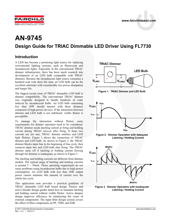
The biggest recent issue of TRIAC dimmable LED bulb is dimmer compatibility. The conventional TRIAC dimmer was originally designed to handle hundreds of watts induced by incandescent bulbs. An LED bulb consuming less than 20W should interact with those dimmers composed of high-power devices. If the interaction between dimmer and LED bulb is not stabilized, visible flicker is perceptible. To manage the interaction without flicker, some requirements for dimmer operation need to be considered. TRIAC dimmer needs latching current at firing and holding current during TRIAC turn-on after firing. If those two currents are not met, TRIAC dimmer misfires and LED Figure 2. Dimmer Operation with Adequate light flickers. Figure 1 shows the connection of TRIAC Latching / Holding Current dimmer and LED bulb. As shown in Figure 2, the TRIAC dimmer blocks input line in the beginning of line cycle, then connects input line and LED bulb after firing. The TRIAC dimmer turns off if latching or holding current flowing through the dimmer is inadequate, as shown in Figure 3. The latching and holding currents are different from dimmer models. The typical range of latching and holding currents is around 5 ~ 50m A. Those operating requirement do not cause problems using incandescent bulbs due to high power consumption. An LED bulb with less than 20W output power cannot maintain this amount of current over the whole line cycle. This application note provides a practical guideline of TRIAC dimmable LED bulb board design. Passive and Figure 3. Dimmer Operation with Inadequate
active bleeder design guides detail how to maintain latching Latching / Holding Current
and holding current without visible flicker. Active damper design improves efficiency by minimizing the count of external components. The input filter design section covers the effect of filter components on PF, THD, and EMI.
© 2011 Fairchild Semiconductor Corporation www.fairchildsemi.com Rev. 1.0.1 • 10/31/11
Page Summary Contents For Fairchild Design Guide for TRIAC Dimmable LED Driver Using FL7730 User Manual
Manual Details
| Brand | Fairchild |
|---|---|
| Pages | 11 |
| File Size | 1.40 MB |
| Published | June 06, 2026 |
Enter the captcha to get the download link:

Frequently Asked Questions
Why does my LED bulb flicker with a conventional TRIAC dimmer?
Low-power LEDs consume less than 20W and cannot maintain the steady latching and holding current (typical range: 5–50mA) required by traditional high-wattage TRIAC dimmers, causing misfires and visible flicker.
What components make up a passive bleeder circuit?
A passive bleeder consists of a resistor (R) connected in series with a capacitor (C), placed between the input power lines.
Why is adding a series resistor required in the bleed design?
The resistor prevents harmful voltage and current spikes from occurring when the capacitor charges quickly, which could otherwise damage the TRIAC dimmer or trigger misfiring.
What are the approximate power quality readings at 120VAC input?
The system achieves a Power Factor (PF) of 0.95 and a Total Harmonic Distortion (THD) of 10.4% when running at 120VAC.