FAIRCHILD AN-6083 Dual PWM Combination Controller High Integration Data Manual User Guide
Summary
Elevate your AC/DC designs with the FAN6791, a highly integrated Dual-PWM Combination Controller crafted for developing high-efficiency smart power supplies. This application note provides deep technical guidance for electrical engineers and designers looking to optimize converter performance. The manual covers critical design elements, including advanced startup circuitry, specialized two-step UVLO protection, proprietary green-mode functionality, and system integration best practices. Learn how to achieve maximum reliability while minimizing standby power consumption in your next generation of electronic products.
Page 1 Text Content
www.fairchildsemi.com
AN-6083 Highly Integrated, Dual-PWM Combination Controller
Introduction
This application note shows the step-by-step process to The FAN6791 is designed for the power supplies to achieve design a high-performance power supply which includes a high efficiency. The highly integrated FAN6791 dual-PWM flyback converter for standby power and a single forward combination controller provides several features to enhance converter for main power. Design considerations and the performance of converters. To minimize standby power mathematical equations are presented, as well as guidelines consumption, a proprietary green-mode function provides for a printed-circuit-board (PCB) layout. off-time modulation to linearly decrease the switching frequency at light-load conditions. With the internal high-
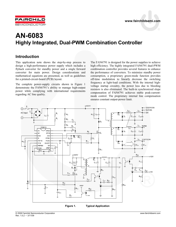
The complete power-supply circuits shown in Figure 1
voltage startup circuitry, the power loss due to bleeding
demonstrate the FAN6791’s ability to manage high-output
resistors is also eliminated. The built-in synchronized slope
power while complying with international requirements
compensation of FAN6791 achieves stable peak-current-
regarding AC line quality.
mode control. The proprietary internal line compensation ensures constant output-power limit.
Figure 1. Typical Application
© 2008 Fairchild Semiconductor Corporation www.fairchildsemi.com Rev. 1.0.2 • 3/11/09
Page Summary Contents For FAIRCHILD AN-6083 Dual PWM Combination Controller High Integration Data Manual User Guide
Manual Details
| Brand | Integration |
|---|---|
| Pages | 9 |
| File Size | 343.30 KB |
| Published | May 29, 2026 |
Enter the captcha to get the download link:

Frequently Asked Questions
How does the FAN6791 maintain stable output under varying Line quality?
It utilizes proprietary internal line compensation and built-in synchronized slope compensation for stable peak-current regulation.
What mechanism protects against short circuits or open-loop conditions?
The device incorporates a special two-step UVLO/OLP mechanism to greatly reduce average input power during fault conditions.
How is the minimum power-on delay time calculated?
It is determined by $t = D_{ON} / (C imes V)$, where V is the turn-on threshold voltage and $D_{ON}$ is the internal timing constant.