Page 1
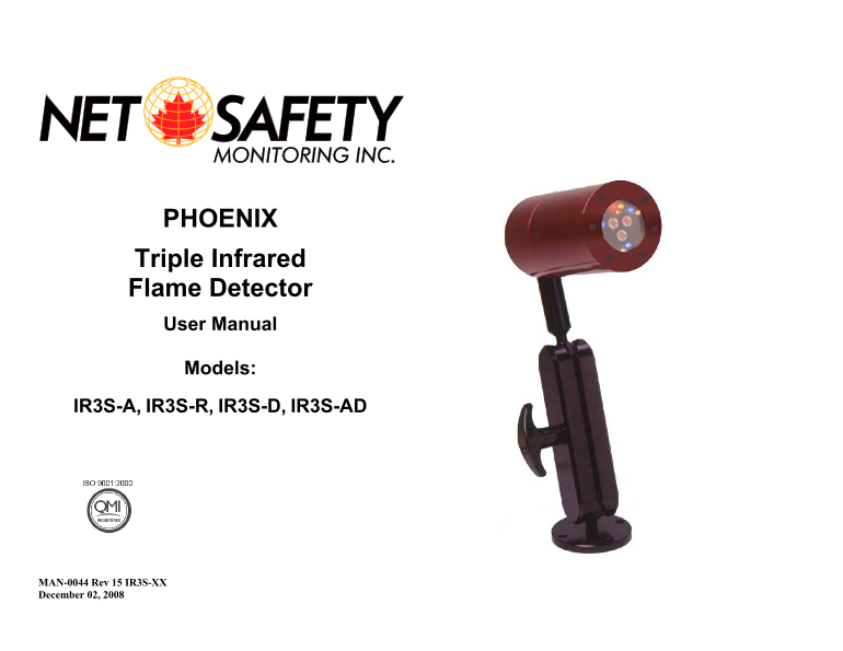
PHOENIX Triple Infrared Flame Detector User Manual Models: IR3S-A, IR3S-R, IR3S-D, IR3S-AD MAN-0044 Rev 15 IR3S-XX December 02, 2008
Page 3
Net Safety Monitoring Inc. IMPORTANT INFORMATION Warranty This manual is for informational purposes only. Although every effort has Net Safety Monitoring Inc., offers a pro-rated 7 year warranty on th...
Page 4
Net Safety Monitoring Inc Get Current Setting ........................................................................................... 17 TABLE OF CONTENTS Modbus Set Up Failure/Reset ...............
Page 5
Net Safety Monitoring Inc. INTRODUCTION Potential Fire Sources The Phoenix, Net Safety’s latest flame detection product, is a triple spectrum The following are examples of some potential fire sources:...
Page 6
Net Safety Monitoring Inc Sensitivity Setting Considerations Sensitivity For practical planning purposes, the “Low” sensitivity setting results The practical application distance is directly related t...
Page 7
Net Safety Monitoring Inc • Tilt detector downward a minimum of 10 to 20° to reduce dirt and Figure 1: Detector and Swivel Mount dust accumulation which could obscure the detector’s viewing window. • ...
Page 8
Net Safety Monitoring Inc Figure 2: Dimensional Drawing FIELD INSTALLATION WARNING: • Wiring codes and regulations may vary. Compliance with regulations is the responsibility of the installer. Wiring ...
Page 9
Net Safety Monitoring Inc Grounding CONNECTING Proper shielding and grounding procedures, for the specific area must be The Phoenix can be either an Analog, Analog/Digital, Relay or Digital followed. ...
Page 10
Net Safety Monitoring Inc Figure 3: Current Output Jumper Placement Figure 4: Current Source and Sink Note the INT and EXT Jumper position for each configuration. INT EXT MAN-0044 Rev 15 IR3S-XX 10 De...
Page 11
Net Safety Monitoring Inc Table 4: Wire Colour Coding — IR3S-A (ANALOG) Table 5: Wire Colour Coding — IR3S-R (RELAY) FLAME DETECTOR WIRE CODING FLAME DETECTOR WIRE CODING Wire Function Wire Function C...
Page 12
Net Safety Monitoring Inc Table 6: Wire Colour Coding—IR3S-AD (ANALOG / DIGITAL) Table 7: Wire Colour Coding — IR3S-D (DIGITAL) FLAME DETECTOR WIRE CODING FLAME DETECTOR WIRE CODING Wire Function Wire...
Page 13
Net Safety Monitoring Inc Time Delay Settings of 3, 5 and 10 seconds DETECTOR SETUP The time delay setting defines the length of time that a fire signal must be SYSTEM SENSITIVITY continuously present...
Page 14
Net Safety Monitoring Inc Relay Table 8: Time Delay and Sensitivity Settings (DIP Switch #1) The relay version Phoenix uses two sets of DIP Switches. DIP Switch #1 Time Delay Sensitivity settings DIP ...
Page 15
Net Safety Monitoring Inc Figure 6: Normally Open or Normally Closed Jumpers. Table 12: Fault Alarm Relay States Relay State Unpowered Powered Alarm (FAULT) shown in Normally Open position Energized/N...
Page 16
Net Safety Monitoring Inc Note: On the Analog /Digital model (AD), ignore the yellow and purple Table 15: Digital Modbus RTU Setting (DIP Switch #1, Position 4) wires for set up. DIP Switch #1 Modbus ...
Page 17
Net Safety Monitoring Inc Figure 7: Phoenix Modbus Set Up DETECTOR FUNCTIONALITY Figure 8: Detector Viewing Window Get Current Setting Click to display the current Modbus set up of the connected Phoen...
Page 18
Net Safety Monitoring Inc MONITOR Condition Status—LEDs The Detector’s status can be determined by monitoring the current output and There are six (6) LEDs used to indicate the status and condition of...
Page 19
Net Safety Monitoring Inc Table 18: RTU Status (Register 40001) Read Only Automatic Digital Zoom (ADZ) RTUfire_power_up 0x0001 0000 0000 0000 0001B Power up delay If a fire is located at an extreme di...
Page 20
Net Safety Monitoring Inc TESTING Clean The Window/Lens Automatic Visual Integrity (VI) Test WARNING: Always bypass Alarm Output and disconnect external To evaluate the cleanliness of the lens and ver...
Page 21
Net Safety Monitoring Inc TROUBLE SHOOT The occurrence of a fault condition may be due to various factors. In order to determine the possible cause of the problem, keep accurate records of these occur...
Page 22
Net Safety Monitoring Inc HOW TO RETURN EQUIPMENT A Material Return Authorization number is required in order to return Also, please ensure a duplicate copy of the packing slip is enclosed inside the ...
Page 23
Net Safety Monitoring Inc Appendix A:ELECTROSTATIC SENSITIVE DEVICE (ESD) Electrostatic discharge (ESD) is the transfer, between bodies, of an In general, exercise accepted and proven precautions norm...
Page 24
Net Safety Monitoring Inc. Appendix B:RESISTANCE TABLE (OHMS) MAN-0044 Rev 15 IR3S-XX 24 December 02, 2008
Page 25
Net Safety Monitoring Inc ppendix C:SPECI FICATION Models IR3S‐A (Analog) I3RS‐R (R elay) IR3S‐AD (Analo g/Digital) Operating Volt age 0 to 32 VDC measu red at the detecto Power Consumpt ion N...
Page 26
Net Safety Monitoring Inc Appendix D:IR3S DATA False Alarm Immunity False Alarm Source Distance Modulated Unmodulated (ft/m) Sunlight direct -------- No Alarm No Alarm Sunlight indirect -------- No Al...
Page 27
Net Safety Monitoring Inc Response Testing w/ Modulated False Alarm Stimuli Present Fire Alarm Source Distance Fire Source Fire Source Distance (ft/m) (ft/m) Sunlight direct --------------- 16" P...
Page 28
Net Safety Monitoring Inc. 2721 Hopewell Place NE, Calgary, AB Canada T1Y 7J7 1‐866‐FIREGAS (347‐3427) | ph. (403) 219‐0688 | fx. (403) 219‐0694 http://www.net‐safety.com | Email: nsmsales@net‐s...