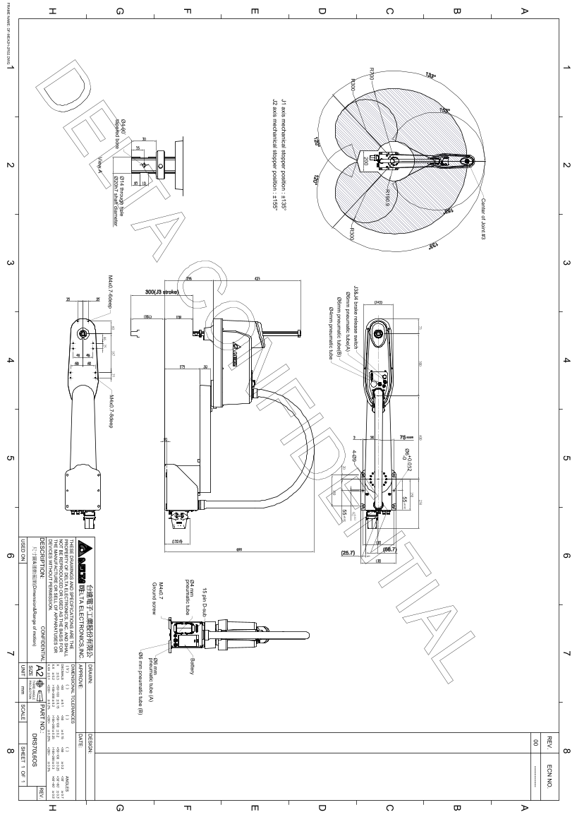
Delta DRS70L6OS Series Robot Appearance and Working Range Dimension Diagram
Summary
This technical documentation provides detailed dimensional drawings and functional specifications for a modular industrial frame system, defining joints, mechanical stoppers, pneumatic connections, and component tolerances across multiple axes. It is designed for engineers and technicians needing precise guidance on assembly, calibration, and maintenance of electromechanical hardware units. Use this manual to ensure the correct integration and optimal performance of complex automated systems requiring high dimensional accuracy.
Manual Details
| Brand | Delta |
|---|---|
| Pages | 1 |
| File Size | 263.27 KB |
| Published | June 06, 2026 |
Enter the captcha to get the download link:

Frequently Asked Questions
What are the dimensional tolerances for drafting elements?
The tolerances vary based on the angle and dimensions, ranging up to $\pm0.5\text{mm}$ for angles between $30^{\circ} - 60^{\circ}$.
Which company owns the intellectual property rights associated with these drawings?
These blueprints are the exclusive property of Delta Electronics, Inc., and reproduction is prohibited without permission.
What kind of mechanical components are included or considered?
The manual details various fittings including pneumatic tubes (A) and (B), a D-sub connector, shafts (Ø20h7), and brake release switches.
What size range does the unit support in certain dimensions?
For elements over 100 to 200 mm, the suggested dimensional tolerance might be $\pm0.2\text{mm}$ or $\pm0.3\text{mm}$.