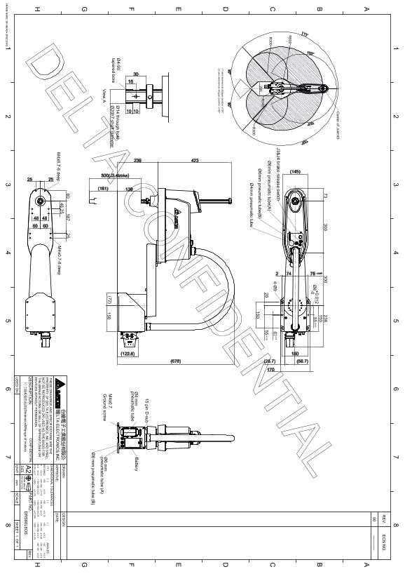
Delta DRS60L6OS Series Robot Appearance and Working Range Dimension Diagram
Summary
This comprehensive manual provides detailed mechanical engineering drawings and precise dimensional specifications for an advanced electromechanical unit. It covers crucial components such as pneumatic tubing interfaces, axis stopper positions, and mounting hardware (e.g., D-sub connectors). Designed primarily for industrial automation engineers and machine builders, this document ensures accurate assembly, calibration, and integration of the component into complex machinery systems, ensuring adherence to strict industry tolerances.
Manual Details
| Brand | Delta |
|---|---|
| Pages | 1 |
| File Size | 249.16 KB |
| Published | June 03, 2026 |
Enter the captcha to get the download link:

Frequently Asked Questions
What is the mechanical stopping range for the J1 and J2 axes?
J1 stops at ±135° and J2 stops at ±155°.
How are pneumatic tubes (A) and (B) specified in the drawing?
Both pneumatic tube (A) and tube (B) are specified as Ø6 mm.
What is one of the general angular dimensional tolerances listed?
There are various ranges, including <30°~ which has an allowance of :`0.1~.